4. This function will consume 3 ~ 5 seconds more when you switch on DTE.
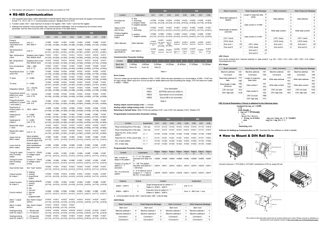
RS-485 Communication
1.DTE supports baud rates 2,400/4,800/9,600/19,200/38,400/57,600/115,200 bps and does not support communication format 7, N, 1/8, E, 2/8, O, 2. Communication protocol = Modbus ASCII or RTU.
2.Function codes: H03 = read maximum 8 words in the register; H06 = write 1 word into the register.
3.Address and contents: Every parameter has 2 communication addresses. One is numbered by the function of the parameter, and the other is by the order of channel (as shown in the table below).
|
|
|
|
| INA |
|
|
|
|
| INB |
|
|
| ||||
|
|
|
|
|
|
|
|
|
|
|
|
|
|
|
|
|
|
|
| Content | Explanation | CH1 |
| CH2 |
| CH3 |
| CH4 |
| CH5 |
| CH6 |
| CH7 |
| CH8 | |
| Present |
| H1000 |
| H1001 |
| H1002 |
| H1003 |
| H1004 |
| H1005 |
| H1006 |
| H1007 |
|
|
|
|
|
|
|
|
|
|
| |||||||||
| temperature | Unit; 0.1 |
|
|
|
|
|
|
|
| ||||||||
| value/input error | See Table 5 | (H1100) |
| (H1200) |
| (H1300) |
| (H1400) |
| (H1500) |
| (H1600) |
| (H1700) |
| (H1800) |
|
| code |
|
|
|
|
|
|
|
|
|
|
|
|
|
|
|
|
|
| Set temperature | Unit: 0.1 | H1008 |
| H1009 |
| H100A |
| H100B |
| H100C |
| H100D |
| H100E |
| H100F |
|
| value | (H1101) |
| (H1201) |
| (H1301) |
| (H1401) |
| (H1501) |
| (H1601) |
| (H1701) |
| (H1801) |
| |
|
|
|
|
|
|
|
|
|
| |||||||||
|
|
|
|
|
|
|
|
|
|
|
|
|
|
|
|
|
|
|
| Max. temperature | Disabled when higher | H1010 |
| H1011 |
| H1012 |
| H1013 |
| H1014 |
| H1015 |
| H1016 |
| H1017 |
|
| value | than default value | (H1102) |
| (H1202) |
| (H1302) |
| (H1402) |
| (H1502) |
| (H1602) |
| (H1702) |
| (H1802) |
|
| Min. temperature | Disabled when lower | H1018 |
| H1019 |
| H101A |
| H101B |
| H101C |
| H101D |
| H101E |
| H101F |
|
| value | than default value | (H1103) |
| (H1203) |
| (H1303) |
| (H1403) |
| (H1503) |
| (H1603) |
| (H1703) |
| (H1803) |
|
|
|
|
|
|
|
|
|
|
|
|
|
|
|
|
|
|
|
|
| Error temperature | H1020 |
| H1021 |
| H1022 |
| H1023 |
| H1024 |
| H1025 |
| H1026 |
| H1027 |
| |
| value | Unit: 0.1°C | (H1104) |
| (H1204) |
| (H1304) |
| (H1404) |
| (H1504) |
| (H1604) |
| (H1704) |
| (H1804) |
|
| Proportional band | 0 ~ 9,999 | H1028 |
| H1029 |
| H102A |
| H102B |
| H102C |
| H102D |
| H102E |
| H102F |
|
| value (Pb) | Unit: 0.1 | (H1105) |
| (H1205) |
| (H1305) |
| (H1405) |
| (H1505) |
| (H1605) |
| (H1705) |
| (H1805) |
|
|
|
|
|
|
|
|
|
|
|
|
|
|
|
|
|
|
|
|
| Ti value | 0 ~ 9,999 | H1030 |
| H1031 |
| H1032 |
| H1033 |
| H1034 |
| H1035 |
| H1036 |
| H1037 |
|
| (H1106) |
| (H1206) |
| (H1306) |
| (H1406) |
| (H1506) |
| (H1606) |
| (H1706) |
| (H1806) |
| ||
|
|
|
|
|
|
|
|
|
|
| ||||||||
|
|
|
|
|
|
|
|
|
|
|
|
|
|
|
|
|
|
|
| Td value | 0 ~ 9,999 | H1038 |
| H1039 |
| H103A |
| H103B |
| H103C |
| H103D |
| H103E |
| H103F |
|
| (H1107) |
| (H1207) |
| (H1307) |
| (H1407) |
| (H1507) |
| (H1607) |
| (H1707) |
| (H1807) |
| ||
|
|
|
|
|
|
|
|
|
|
| ||||||||
| Integration default | 0.0 ~ 100.0% | H1040 |
| H1041 |
| H1042 |
| H1043 |
| H1044 |
| H1045 |
| H1046 |
| H1010 |
|
| Unit: 0.1% | (H1108) |
| (H1208) |
| (H1308) |
| (H1408) |
| (H1508) |
| (H1608) |
| (H1708) |
| (H1808) |
| |
|
|
|
|
|
|
|
|
|
| |||||||||
|
|
|
|
|
|
|
|
|
|
|
|
|
|
|
|
|
|
|
| Proportional control | 0.0 ~ 100.0% | H1048 |
| H1049 |
| H104A |
| H104B |
| H104C |
| H104D |
| H104E |
| H104F |
|
| offset error value, | Unit: 0.1% | (H1109) |
| (H1209) |
| (H1309) |
| (H1409) |
| (H1509) |
| (H1609) |
| (H1709) |
| (H1809) |
|
| when Ti = 0 |
|
|
|
|
|
|
|
| |||||||||
|
|
|
|
|
|
|
|
|
|
|
|
|
|
|
|
|
| |
| Proportional band | 0.01 ~ 99.99 | H1050 |
| H1051 |
| H1052 |
| H1053 |
| H1054 |
| H1055 |
| H1056 |
| H1057 |
|
| coefficient of output |
|
|
|
|
|
|
|
| |||||||||
| Unit: 0.01 | (H110A) |
| (H120A) |
| (H130A) |
| (H140A) |
| (H150A) |
| (H160A) |
| (H170A) |
| (H180A) |
| |
| 1 and output 2 |
|
|
|
|
|
|
|
|
|
|
|
|
|
|
|
|
|
| Dead band of |
| H1058 |
| H1059 |
| H105A |
| H105B |
| H105C |
| H105D |
| H105E |
| H105F |
|
| control output 1 & |
|
|
|
|
|
|
|
| |||||||||
| (H110B) |
| (H120B) |
| (H130B) |
| (H140B) |
| (H150B) |
| (H160B) |
| (H170B) |
| (H180B) |
| ||
| output 2. |
|
|
|
|
|
|
|
|
| ||||||||
|
|
|
|
|
|
|
|
|
|
|
|
|
|
|
|
|
| |
|
|
|
|
|
|
|
|
|
|
|
|
|
|
|
|
|
|
|
| Hysteresis for | 0 ~ 9,999 | H1060 |
| H1061 |
| H1062 |
| H1063 |
| H1064 |
| H1065 |
| H1066 |
| H1067 |
|
| output 1 | Unit: 0.1% | (H110C) |
| (H120C) |
| (H130C) |
| (H140C) |
| (H150C) |
| (H160C) |
| (H170C) |
| (H180C) |
|
|
|
|
|
|
|
|
|
|
|
|
|
|
|
|
|
|
|
|
| Hysteresis for | 0 ~ 9,999 | H1068 |
| H1069 |
| H106A |
| H106B |
| H106C |
| H106D |
| H106E |
| H106F |
|
| output 2 | Unit: 0.1% | (H110D) |
| (H120D) |
| (H130D) |
| (H140D) |
| (H150D) |
| (H160D) |
| (H170D) |
| (H180D) |
|
| Read/write output | Unit: 0.1 % | H1070 |
| H1071 |
| H1072 |
| H1073 |
| H1074 |
| H1075 |
| H1076 |
| H1077 |
|
| 1 value | (H110E) |
| (H120E) |
| (H130E) |
| (H140E) |
| (H150E) |
| (H160E) |
| (H170E) |
| (H180E) |
| |
|
|
|
|
|
|
|
|
|
| |||||||||
|
|
|
|
|
|
|
|
|
|
|
|
|
|
|
|
|
|
|
| Read/write output | Unit: 0.1 % | H1078 |
| H1079 |
| H107A |
| H107B |
| H107C |
| H107D |
| H107E |
| H107F |
|
| 2 value | (H110F) |
| (H120F) |
| (H130F) |
| (H140F) |
| (H150F) |
| (H160F) |
| (H170F) |
| (H180F) |
| |
|
|
|
|
|
|
|
|
|
| |||||||||
| Upper limit for | Alarm enabled | H1080 |
| H1081 |
| H1082 |
| H1083 |
| H1084 |
| H1085 |
| H1086 |
| H1087 |
|
| when temperature |
|
|
|
|
|
|
|
| |||||||||
| alarm output | (H1110) |
| (1210) |
| (H1310) |
| (H1410) |
| (H1510) |
| (H1610) |
| (H1710) |
| (H1810) |
| |
| exceeds upper limit |
|
|
|
|
|
|
|
| |||||||||
|
|
|
|
|
|
|
|
|
|
|
|
|
|
|
|
|
| |
|
| Alarm enabled | H1088 |
| H1089 |
| H108A |
| H108B |
| H108C |
| H108D |
| H108E |
| H108F |
|
| Lower limit for | when temperature |
|
|
|
|
|
|
|
| ||||||||
| alarm output | falls below lower | (H1111) |
| (H1211) |
| (H1311) |
| (H1411) |
| (H1511) |
| (H1611) |
| (H1711) |
| (H1811) |
|
|
| limit |
|
|
|
|
|
|
|
|
|
|
|
|
|
|
|
|
| Tuning for upper | Current (4 ~ 20mA) | H1090 |
| H1091 |
| H1092 |
| H1093 |
| H1094 |
| H1095 |
| H1096 |
| H1097 |
|
| limit of analog | or voltage output |
|
|
|
|
|
|
|
| ||||||||
| (H1112) |
| (H1212) |
| (H1312) |
| (H1412) |
| (H1512) |
| (H1612) |
| (H1712) |
| (H1812) |
| ||
| output | tuning |
|
|
|
|
|
|
|
| ||||||||
|
|
|
|
|
|
|
|
|
|
|
|
|
|
|
|
| ||
| Tuning for lower | Current (4 ~ 20mA) | H1098 |
| H1099 |
| H109A |
| H109B |
| H109C |
| H109D |
| H109E |
| H109F |
|
| limit of analog | or voltage output |
|
|
|
|
|
|
|
| ||||||||
| (H1113) |
| (H1213) |
| (H1313) |
| (H1413) |
| (H1513) |
| (H1613) |
| (H1713) |
| (H1813) |
| ||
| output | tuning |
|
|
|
|
|
|
|
| ||||||||
|
|
|
|
|
|
|
|
|
|
|
|
|
|
|
|
| ||
| Input sensor type | See “Input” section | H10A0 |
| H10A1 |
| H10A2 |
| H10A3 |
| H10A4 |
| H10A5 |
| H10A6 |
| H10A7 |
|
| (H1114) |
| (H1214) |
| (H1314) |
| (H1414) |
| (H1514) |
| (H1614) |
| (H1714) |
| (H1814) |
| ||
|
|
|
|
|
|
|
|
|
|
| ||||||||
|
|
|
|
|
|
|
|
|
|
|
|
|
|
|
|
|
|
|
| Output function | 0: heating | H10A8 |
| H10A9 |
| H10AA |
| H10AB |
| H10AC |
| H10AD |
| H10AE |
| H10AF |
|
| 1: cooling |
|
|
|
|
|
|
|
| |||||||||
| for output 1 | 2: proportional | (H1115) |
| (H1215) |
| (H1315) |
| (H1415) |
| (H1515) |
| (H1615) |
| (H1715) |
| (H1815) |
|
|
| output |
|
|
|
|
|
|
|
|
|
|
|
|
|
|
|
|
| Output function | 0: heating (default) | H10B0 |
| H10B1 |
| H10B2 |
| H10B3 |
| H10B4 |
| H10B5 |
| H10B6 |
| H10B7 |
|
| 1: cooling |
|
|
|
|
|
|
|
| |||||||||
| for output 2 | (H1116) |
| (H1216) |
| (H1316) |
| (H1416) |
| (H1516) |
| (H1616) |
| (H1716) |
| (H1816) |
| |
| 2: alarm |
|
|
|
|
|
|
|
| |||||||||
|
|
|
|
|
|
|
|
|
|
|
|
|
|
|
|
|
| |
|
|
|
|
|
|
|
|
|
|
|
|
|
|
|
|
|
|
|
|
| 0: PID |
|
|
|
|
|
|
|
|
|
|
|
|
|
|
|
|
|
| 1: | H10B8 |
| H10B9 |
| H10BA |
| H10BB |
| H10BC |
| H10BD |
| H10BE |
| H10BF |
|
| Control method | 2: manual |
|
|
|
|
|
|
|
| ||||||||
| (H1117) |
| (H1217) |
| (H1317) |
| (H1417) |
| (H1517) |
| (H1617) |
| (H1717) |
| (H1817) |
| ||
|
| 3: PID |
|
|
|
|
|
|
|
| ||||||||
|
|
|
|
|
|
|
|
|
|
|
|
|
|
|
|
|
| |
|
| programmable |
|
|
|
|
|
|
|
|
|
|
|
|
|
|
|
|
| Alarm 1 output | See “Alarm Output” | H10C0 |
| H10C1 |
| H10C2 |
| H10C3 |
| H10C4 |
| H10C5 |
| H10C6 |
| H10C7 |
|
| mode | section | (H1118) |
| (H1218) |
| (H1318) |
| (H1418) |
| (H1518) |
| (H1618) |
| (H1718) |
| (H1818) |
|
|
|
|
|
|
|
|
|
|
|
|
|
|
|
|
|
|
|
|
| Alarm 2 output | See “Alarm Output” | H10C4 |
| H10C5 |
| H10C6 |
| H10C7 |
|
|
|
|
|
|
|
|
|
| mode | section | (H1518) |
| (H1618) |
| (H1718) |
| (H1818) |
|
|
|
|
|
|
|
|
|
| Heating/cooling | 1 ~ 99 seconds | H10C8 |
| H10C9 |
| H10CA |
| H10CB |
| H10CC |
| H10CD |
| H10CE |
| H10CF |
|
| cycle for output 1 | 0 = 0.5 second | (H1119) |
| (H1219) |
| (H1319) |
| (H1419) |
| (H1519) |
| (H1619) |
| (H1719) |
| (H1819) |
|
|
|
|
|
|
|
|
|
|
|
|
|
|
|
|
|
|
|
|
| Heating/cooling | 1 ~ 99 seconds | H10D0 |
| H10D1 |
| H10D2 |
| H10D3 |
| H10D4 |
| H10D5 |
| H10D6 |
| H10D7 |
|
| cycle for output 2 | 0 = 0.5 second | (H111A) |
| (H121A) |
| (H131A) |
| (H141A) |
| (H151A) |
| (H161A) |
| (H171A) |
| (H181A) |
|
|
|
|
|
|
|
|
|
|
|
|
|
|
|
|
|
|
|
|
|
|
| INA |
|
| INB |
| |||
|
|
|
|
|
|
|
|
|
| |
Content | Explanation | CH1 | CH2 | CH3 | CH4 | CH5 | CH6 | CH7 | CH8 | |
|
|
|
|
|
|
|
|
|
| |
| 0: stop | H10D8 | H10D9 | H10DA | H10DB | H10DC | H10DD | H10DE | H10DF | |
Run/Stop the | 1: executing | |||||||||
control | 2: program stops | (H111B) | (H121B) | (H131B) | (H141B) | (H151B) | (H161B) | (H171B) | (H181B) | |
| 3: program pauses |
|
|
|
|
|
|
|
| |
Status of PID | 0: stop | H10E0 | H10E1 | H10E2 | H10E3 | H10E4 | H10E5 | H10E6 | H10E7 | |
1: executing | (H111C) | (H121C) | (H131C) | (H141C) | (H151C) | (H161C) | (H171C) | (H181C) | ||
|
|
|
|
|
|
|
|
|
| |
Positive/negative | 0: positive | H10E8 | H10E9 | H10EA | H10EB | H10EC | H10ED | H10EE | H10EF | |
proportional | ||||||||||
1: negative (slope) | (H111D) | (H121D) | (H131D) | (H141D) | (H151D) | (H161D) | (H171D) | (H181D) | ||
output | ||||||||||
|
|
|
|
|
|
|
|
| ||
|
|
|
|
|
|
|
|
|
| |
|
| H10F0 | H10F1 | H10F2 | H10F3 | H10F4 | H10F5 | H10F6 | H10F7 | |
Other statuses | Other statuses | Open special | Return to | |||||||
Temperature | function | default | Reserved | Reserved | Reserved | Reserved | Reserved | |||
|
| |||||||||
|
| unit | (H1234) | (H1357) |
|
|
|
|
| |
|
|
|
|
|
|
|
| |||
Communication | See Table 4 | H10F8 | H10F9 | H10FA | H10FB | H10FC | H10FD | H10FE | H10FF | |
Auto ID | ASCII = 0 | 8 bits=0 | 2 stop=0 | Address | ||||||
specifications | Reserved | Baud rate | Parity | |||||||
| setup | RTU = 1 | 7 bits=1 | 1 stop=1 | 1 ~ 247 | |||||
|
|
|
|
| ||||||
Communication Parameter Setting: |
|
|
|
|
| ||
Content | 0 | 1 | 2 | 3 | 4 | 5 | 6 |
Baud rate | 2,400bps | 4,800bps | 9,600bps | 19,200bps | 38,400bps | 57,600bps | 115,200bps |
Parity bit | None (N) | Even (E) | Odd (O) |
|
|
|
|
Table 4
Error Codes:
The error codes can be read from address H1000 ~ H1007. When the input operation is in normal status, H1000 ~ H1007 are for input values. When input error occurs (except for stable status and input exceeding the range), DTE will read error codes in H8001 ~ H8002.
H1000 | Error description |
|
|
H8001 | EEPROM cannot be written in. |
H8002 | Input sensor is not connected. |
H8003 | Group INB is not connected. |
|
|
Table 5
Analog output current tuning scale: 1μA/scale
Analog output voltage tuning scale: 1mV/scale
Returning to Default Value: Write H1234 into address H10F1 and H1357 into address H10F2. Restart DTE.
Programmable Communication Parameter Setting:
|
|
|
|
|
|
|
|
|
|
|
|
|
|
|
| INA |
|
|
|
|
| INB |
|
|
|
| ||||||
|
|
|
|
|
|
|
|
|
|
|
|
|
|
|
|
|
|
|
|
|
|
|
|
|
|
|
|
|
|
|
|
|
|
| Content |
|
|
|
|
| Explanation |
| CH1 |
|
| CH2 |
| CH3 | CH4 |
| CH5 |
| CH6 |
| CH7 | CH8 | |||||||||
|
| Read remaining time of the step |
| Unit: sec |
| H111E |
|
| H121E |
| H131E |
| H141E |
| H151E |
| H161E |
| H171E |
| H181E |
| ||||||||||
|
|
|
|
|
|
|
|
|
|
|
|
| ||||||||||||||||||||
|
|
|
|
|
|
|
|
|
|
|
|
|
|
|
|
|
|
|
|
|
|
|
|
|
|
|
|
|
|
|
|
|
|
| Read remaining time of the step |
| Unit: min |
| H111F |
|
| H121F |
| H131F |
| H141F |
| H151F |
| H161F |
| H171F |
| H181F |
| ||||||||||
|
| Read the NO. of the current |
| 0 ~ 7 |
| H1120 |
|
| H1220 |
| H1320 |
| H1420 |
| H1520 |
| H1620 |
| H1720 |
| H1820 |
| ||||||||||
|
| pattern |
|
|
|
|
|
|
|
|
|
|
|
|
|
|
| |||||||||||||||
|
|
|
|
|
|
|
|
|
|
|
|
|
|
|
|
|
|
|
|
|
|
|
|
|
|
|
|
|
|
|
| |
|
| Read the NO. of the current step | 0 ~ 7 |
| H1121 |
|
| H1221 |
| H1321 |
| H1421 |
| H1521 |
| H1621 |
| H1721 |
| H1821 |
| |||||||||||
|
|
|
|
|
|
|
|
|
|
|
|
|
|
|
|
|
|
|
|
|
|
|
|
|
|
|
|
|
|
|
|
|
|
| NO. of start pattern |
|
|
|
|
| 0 ~ 7 |
| H1122 |
|
| H1222 |
| H1322 |
| H1422 |
| H1522 |
| H1622 |
| H1722 |
| H1822 |
| ||||||
|
|
|
|
|
|
|
|
|
|
|
|
|
|
|
|
|
|
|
|
|
|
|
|
|
|
|
|
|
|
|
|
|
|
| NO. of start step |
|
|
|
|
| 0 ~ 7 |
| H1123 |
|
| H1223 |
| H1323 |
| H1423 |
| H1523 |
| H1623 |
| H1723 |
| H1823 |
| ||||||
| Programmable Parameter Setting: |
|
|
|
|
|
|
|
|
|
|
|
|
|
|
|
|
|
|
|
|
|
|
| ||||||||
|
|
|
|
|
|
|
|
|
|
| Pattern Pattern Pattern Pattern Pattern Pattern Pattern Pattern | |||||||||||||||||||||
|
| Content |
|
| Explanation |
| ||||||||||||||||||||||||||
|
|
|
| 0 |
|
|
| 1 | 2 |
| 3 | 4 |
| 5 | 6 |
| 7 |
|
| |||||||||||||
|
|
|
|
|
|
|
|
|
|
|
|
|
|
|
|
|
| |||||||||||||||
|
| Max. number of |
|
| 0 ~ 7 = N: The pattern |
| H2068 |
|
| H2069 |
| H206A |
| H206B |
| H206C |
| H206D |
| H206E |
| H206F |
| |||||||||
|
|
|
| executes from step 0 to |
|
|
|
|
|
|
|
|
|
| ||||||||||||||||||
|
| steps in the pattern |
|
|
|
|
|
|
|
|
|
|
|
| ||||||||||||||||||
|
|
|
| N. |
|
|
|
|
|
|
|
|
|
|
|
|
|
|
|
|
|
|
|
|
|
|
|
|
|
| ||
|
|
|
|
|
|
|
|
|
|
|
|
|
|
|
|
|
|
|
|
|
|
|
|
|
|
|
|
|
|
| ||
|
|
|
|
|
|
|
|
|
|
|
|
|
|
|
|
|
|
|
|
|
|
|
|
|
|
|
|
|
|
| ||
|
| Number of cycles of |
|
| 0 ~ 199: The pattern |
| H2070 |
|
| H2071 |
| H2072 |
| H2073 |
| H2074 |
| H2075 |
| H2076 |
| H2077 |
| |||||||||
|
| pattern 0 ~ 7 |
| has been executed for 1 |
|
|
|
|
|
|
|
|
|
| ||||||||||||||||||
|
| execution |
| ~ 200 times |
|
|
|
|
|
|
|
|
|
|
|
|
|
|
|
|
|
|
|
|
|
|
| |||||
|
| NO. of current link |
|
| 0 ~ 8: 8 refers to end of |
|
|
|
|
|
|
|
|
|
|
|
|
|
|
|
|
|
|
|
|
|
|
| ||||
|
|
| program; 0 ~ 7 refer to |
| H2078 |
|
| H2079 |
| H207A |
| H207B |
| H207C |
| H207D |
| H207E |
| H207F |
| |||||||||||
|
| pattern |
|
|
|
|
|
|
|
|
|
|
| |||||||||||||||||||
|
|
| the NO. of next pattern |
|
|
|
|
|
|
|
|
|
|
|
|
|
|
|
|
|
|
|
|
|
|
| ||||||
|
|
|
|
|
|
|
|
|
|
|
|
|
|
|
|
|
|
|
|
|
|
|
|
|
|
| ||||||
|
| Address |
|
| Default |
|
|
| Content |
|
|
|
|
|
|
|
| Explanation |
|
|
|
| ||||||||||
|
| 2000H ~ 203FH |
| 0 |
|
|
| Target temperatures for pattern 0 ~ 7 |
|
| Unit: 0.1°C |
|
|
|
|
|
|
| ||||||||||||||
|
|
|
|
|
|
|
|
|
|
|
|
|
|
| ||||||||||||||||||
|
|
|
|
|
| Pattern 0: 2000H ~ 2007H |
|
|
|
|
|
|
|
|
|
|
|
| ||||||||||||||
|
|
|
|
|
|
|
|
|
|
|
|
|
|
|
|
|
|
|
|
|
|
|
|
| ||||||||
|
| 2080H ~ 20BFH |
| 0 |
|
|
| Execution time for pattern 0 ~ 7 |
|
| Time: 0 ~ 900 (Unit: 1 min) |
|
|
|
| |||||||||||||||||
|
|
|
|
|
| Pattern 0: 2080H ~ 2087H |
|
|
|
|
|
|
|
|
| |||||||||||||||||
|
|
|
|
|
|
|
|
|
|
|
|
|
|
|
|
|
|
|
|
|
|
|
|
| ||||||||
|
|
|
|
|
|
|
|
|
|
|
|
|
|
|
|
|
|
|
|
|
|
|
|
| ||||||||
| 4. Communication format: H03 = read bit data; H06 = write bit data |
|
|
|
|
|
|
|
|
|
|
|
|
|
|
|
| |||||||||||||||
| ASCII Mode: |
|
|
|
|
|
|
|
|
|
|
|
|
|
|
|
|
|
|
|
|
|
|
|
|
|
|
|
|
|
| |
|
| Read Command |
|
|
| Read Response Message |
|
|
| Write Command |
|
|
| Write Response Message | ||||||||||||||||||
|
| Start word |
|
| ’:’ |
|
| Start word |
|
|
| ’:’ |
|
|
| Start word |
| ’:’ |
|
| Start word |
| ’:’ |
| ||||||||
|
|
|
|
|
|
|
|
|
|
|
|
|
|
|
|
|
| |||||||||||||||
|
|
|
|
|
|
|
|
|
|
|
|
|
|
|
|
|
|
|
| |||||||||||||
|
| Machine address 1 |
|
| ‘0’ |
| Machine address 1 |
| ‘0’ |
| Machine address 1 |
| ‘0’ |
| Machine address 1 |
| ‘0’ |
|
| |||||||||||||
|
|
|
|
|
|
|
|
|
|
|
|
|
|
|
|
|
|
|
| |||||||||||||
|
| Machine address 0 |
|
| ‘1’ |
| Machine address 0 |
| ‘1’ |
| Machine address 0 |
| ‘1’ |
| Machine address 0 |
| ‘1’ |
|
| |||||||||||||
|
| Command 1 |
|
| ‘0’ |
|
| Command 1 |
|
|
| ‘0’ |
|
|
| Command 1 |
| ‘0’ |
|
| Command 1 |
| ‘0’ |
|
| |||||||
|
| Command 0 |
|
| ‘3’ |
|
| Command 0 |
|
|
| ‘3’ |
|
|
| Command 0 |
| ‘6’ |
|
| Command 0 |
| ‘6’ |
|
| |||||||
|
|
|
|
|
|
|
|
|
|
|
|
|
|
|
|
|
|
|
|
|
|
|
|
|
|
|
|
|
|
|
|
|
Read Command |
| Read Response Message | Write Command |
| Write Response Message | |||
|
|
|
|
|
|
|
| |
| ‘1’ | Length of response data | ‘0’ |
| ‘1’ |
| ‘1’ | |
Read start address of | ‘0’ | (byte) | ‘4’ | Data address | ‘0’ | Data address | ‘0’ | |
data/bit | ‘0’ |
| ‘0’ | ‘0’ | ‘0’ | |||
|
|
| ||||||
| ‘0’ | Data content in H1000 | ‘1’ |
| ‘1’ |
| ‘1’ | |
|
|
|
|
|
|
| ||
| ‘0’ | ‘F’ |
| ‘0’ |
| ‘0’ | ||
|
|
|
| |||||
|
|
|
|
|
|
|
| |
Read length of data/bit | ‘0’ |
| ‘4’ | Write data content | ‘3’ | Write data content | ‘3’ | |
(word/bit) | ‘0’ |
| ‘0’ | ‘E’ | ‘E’ | |||
|
|
| ||||||
| ‘2’ | Data content in H1001 | ‘0’ |
| ‘8’ |
| ‘8’ | |
|
|
|
|
|
|
| ||
LRC1 check | ‘E’ | ‘0’ | LRC1 check | ‘F’ | LRC1 check | ‘F’ | ||
| ||||||||
|
|
|
|
|
|
|
| |
LRC0 check | ‘A’ |
| ‘0’ | LRC0 check | ‘D’ | LRC0 check | ‘D’ | |
End word 1 | CR | LRC1 check | ‘0’ | End word 1 | CR | End word 1 | CR | |
|
|
|
|
|
|
|
| |
End word 0 | LF | LRC0 check | ‘3’ | End word 0 | LF | End word 0 | LF | |
|
|
|
|
|
|
|
| |
|
| End word 1 | CR |
|
|
|
| |
|
| End word 0 | LF |
|
|
|
| |
LRC Check:
Sum up the contents from “machine address” to “data content”, e.g. H01 + H03 + H10 + H00 + H00 + H02 = H16. Obtain 2’scomplement H EA.
RTU Mode:
Read Command |
| Read Response Message | Write Command |
| Write Response Message | |||
|
|
|
|
|
|
|
| |
Machine address | H01 | Machine address | H01 | Machine address | H01 | Machine address | H01 | |
Command | H03 | Command | H03 | Command | H06 | Command | H06 | |
Read start address of | H10 | Length of response | H04 | Write data address | H10 | Write data address | H10 | |
data | H00 | data (byte) | H01 | H01 | ||||
|
|
| ||||||
|
|
|
|
|
|
|
| |
Read length of data | H00 | Data content 1 | H01 | Write data content | H03 | Write data content | H03 | |
(bit/word) | H02 | HF4 | H20 | H20 | ||||
|
|
| ||||||
CRC low byte | HC0 | Data content 2 | H03 | CRC low byte | HDD | CRC low byte | HDD | |
|
|
|
|
|
|
| ||
CRC high byte | HCB | H20 | CRC high byte | HE2 | CRC high byte | HE2 | ||
| ||||||||
|
|
|
|
|
|
|
| |
|
| CRC low byte | HBB |
|
|
|
| |
|
| CRC high byte | H15 |
|
|
|
| |
CRC (Cyclical Redundancy Check) is obtained by the following steps:
unsigned int reg_crc = 0xffff; i = 0;
while
{reg_crc ^= RTUData[i];
i++;
for (j = 0; j < 8; j++) |
| |
{ | if (reg_crc & 0x01) | reg_crc = (reg_crc >> 1) ^ 0xA001; |
} | else | reg_crc = reg_crc >> 1; |
|
| |
}
return(reg_crc);
Software for Setting up Communication on PC: Download the free software on Delta’s website.
How to Mount & DIN Rail Size
Connect maximum 7 DTC2000 or DTC2001 controllers to DTE by using DIN rail.
The content of this instruction sheet may be revised without prior notice. Please consult our distributor or download the most updated version at http://www.delta.com.tw/industrialautomation.