Mode | Alarm Type | Alarm Output Operation |
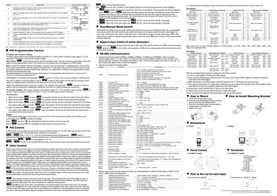
8 | Standby upper/lower limit alarm: Alarm will be enabled when the PV reaches SV and | ON | | | | | | | | | |
| | | | | | | |
OFF | | | | | | | | | | |
exceeds SV + AL-H or falls below SV – AL-L. | | | AL-L | SV | AL-H |
| | | | | |
| | | | | | |
9 | Upper limit standby alarm: Alarm will be enabled when the PV reaches SV and exceeds | ON | | | | | |
| | | | |
OFF | | | | | | | | | | | |
SV + AL-H. | | | | | | | SV | AL-H |
| | | | | | | | |
| | | | | | | | | |
10 | Lower limit standby alarm: Alarm will be enabled when the PV reaches SV and falls below | ON | | | | | | | | | | |
| | | | | | | |
OFF | | | | | | | | | | | | |
SV – AL-L. | | | | AL-L | SV | | | |
| | | | | | | | |
| | | | | | | | | |
11 | Upper limit hysteresis alarm: Alarm will be enabled when the PV exceeds SV + AL-H. | ON | | | | | |
| | | | |
OFF | | | | | | | | | | |
Alarm will be disabled when the PV falls below SV + AL-L. | | | | | | AL-L | AL-H |
| | | | | | | | |
| | | | | | | | | |
12 | Lower limit hysteresis alarm: Alarm will be enabled when the PV falls below SV – AL-H. | ON | | | | | | | | |
| | | | | | | |
OFF | | | | | | | | | |
Alarm will be disabled when the PV exceeds SV – AL-L. | | AL-H | AL-L | | | |
| | | | | | | | |
| | | | | | | | | |
14Programmable STOP: Alarm will be enabled when the program is in STOP status.
15Programmable RAMP UP: Alarm will be enabled when the program is in RAMP UP status.
16Programmable RAMP DOWN: Alarm will be enabled when the program is in RAMP DOWN status.
17Programmable SOAK: Alarm will be enabled when the program is in SOAK status.
18Programmable RUN: Alarm will be enabled when the program is in RUN status.
Note: AL-H and AL-L include AL1H, AL2H and AL1L, AL2L. There is no mode 13 (reserved for CT function).
PID Programmable Control
Functions and Parameter Setting:
The PID programmable control includes 8 patterns (Pattern 0 ~ 7). Each pattern contains 8 steps (Step 0 ~ 7) and parameters: link pattern, cycle and the number of steps.
Start Pattern  : This parameter can be set in the operation mode. The user can set up which pattern is the start pattern for the programmable control. This function is only available when the program is in STOP status.
Step: Includes the settings of the two parameters, set point X and execution time T, indicating that the set point (SV) has to rise to temperature X after the period of execution time T. If the result of the set point X is the same as that of the previous setting, the process is called Soak; otherwise, it is called Ramp. Therefore, the programmable control is also known as Ramp/Soak control.
The default setting of the first step program is Soak control. The temperature will first rise to the set point X and remain at X. The total execution time is T.
Link Pattern: For example, if the parameter  is set as 2, it refers to the execution of pattern 2 will follow the
execution of pattern 0. If the link pattern is set as  , it refers to the program will end after the execution of the pattern is completed and the temperature will remain at the SV for the last step.
Cycle: The additional number of cycles for a pattern. For example, if the parameter  is set as 2, it refers to pattern 4 has to execute twice additionally, totaling the executions to 3 times including the original one.
The Number of Steps: The number of steps in each pattern (range: 0 ~ 7). For example, if the parameter  is set as 2, it refers to pattern 7 will execute step 0 ~ step 2 and other steps will not be executed.
The Execution:
1.When the parameter  is set as
  , the program will start its execution from step 0 of the start pattern.
2.When the parameter  is set as
  , the program will stop and the control output will be disabled.
3.When the parameter  is set as
  , the program will stop and the temperature will stop at the SV before
the program stops. When you select  again, the program will execute again from step 0 of the start pattern.
4.When the parameter  is set as
  , the program will stop and the temperature will stop at the SV before
the program stops. When you select  again, the program will resume the step before the program stops and execute by the remaining time.
Display:
In PID programmable control, some SVs are re-set as P-XX. P refers to the current pattern and XX refers to the
current step. Press 
 to modify the display.
Select  and press
  . SV will display the target temperature for the current step.
Select  and press
  . SV will display the remaining time of the current step.
PID Control
In PID control, you can select any one of the 4 groups of PID parameter (P, I, D, IOF). After auto-tuning, the PID value and the temperature SV will be stored into the selected PID parameter.
 ~
~  : PIDn, n = 0 ~ 4. 0 ~ 3 are the corresponding selected PID parameter.
  refers to
auto-selected PID and the program will automatically select a most useful PID parameter based on the current SV. SV
displays will be  ~
~  corresponding to n = 0 ~ 3.
~  : The SV for the selected PID parameter, can be set by the user or auto-generated by auto-tuning.
Valve Control
Heaters and coolers can be used to control the temperature and the openness of the valve in order to control the flow of the medium. Current and voltage can control the openness of the valve; however, the most direct and economic way to control the openness of the valve is the relay. To control the valve by voltage and current, you can use the DTB series analog output controller. If you tend to use relay for the control output, you have to choose the valve function in DTV series. The two control outputs are relay output for the forward/reverse running of the motor to drive the opening and closing of the valve. Control output1 controls the opening of the valve and control output 2 controls the closing of the valve in order to adjust the position of the valve. In order to detect the position of the valve, DTV is able to receive “feedback signal” and “no feedback signal”. When there is no feedback signal and the valve is fully open, control output 1 will output continuously. If at the moment the valve is fully closed, control output 2 will output continuously. If the valve you use is with feedback output, you can connect the output of the valve to the feedback part of DTV and set
 to On to precisely control the openness of the valve. If there is no feedback signal or the feedback signal is incorrect, and the pre-set openness of the valve is not reached after twice as long as the time set in the parameter
 , the program will automatically switch back to the no feedback state. To ensure the correctness of the valve control, please make sure that you have set up the parameters below:
 : Time required from the valve fully closed to fully open. This parameter has to be correct when the valve is without feedback signal; otherwise, the accuracy for the temperature control will be affected. The PID control will correspond to the openness of the valve according to the setting of this parameter.
 : DeadBand value of the valve. The parameter is to prevent frequent movement of the valve. For example, assume the DeadBand is 4%, PID control will correspond to the openness of the valve within 4% and the valve will not move within the range unless the value is accumulated and exceeds 4%. If the Deadband value is too small and the valve is set to have feedback signals, moving back and forth of the valve will shorten the life of the valve motor.
 : With or without feedback signals.
When  is set as “On”, it refers to “with feedback signals” and the following parameters will be displayed.
a) : Automatically adjusting the upper/lower limit of the valve feedback. This parameter will only be displayed
when  is set as
  . When this parameter is set as On, the relay will enable the forward and reverse running of the motor in order to calculate the time needed from the valve fully closed to fully open and the feedback signal of fully closed and open. The feedback signal is the hardware D/A value of the valve control, which is for the calculation of the valve controller.
b) : Upper limit of the valve signal. Set
  as “On”, can be set automatically or manually.
c) : Lower limit of the valve signal. Set
  as ”On”, can be set automatically or manually.
Auto/Manual Mode Switch
A/M indicator On refers to manual mode; A/M indicator Off refers to auto mode. Besides On/Off, PID, programmable and manual controls, the valve control is also able to forcibly switch to manual control (fixing the openness of the
valve, unit: % from valve fully closed to fully open) when in PID control mode. You simply need to press  in PID
control mode to switch to manual mode and A/M indicator will be On. Press  again to return to PID control and A/M indicator will be Off.
Upper/Lower Limits of Valve Openness
Assume we would like the maximum openness of the valve to be 80% and the minimum to be 20%, set the parameter


 as 80 and
  as 20, and the valve openness of PID control, programmable control and manual control will fall within this range.
RS-485 Communication
1.Supports transmission speed 2,400bps, 4,800bps, 9,600bps, 19,200bps and 38,400bps; does not support communication format 7, N, 1/8, E, 2/8, O, 2. Communication protocol: Modbus (ASCII or RTU). Function: 03H (able to read max. 8 words in the register), 06H (able to write 1 word into the register), 01H (able to read max. 16 bits of data), 05H (able to write 1 bit into the register).
2.Address and content of the data register.
Address | | Content | | Explanation |
| | | Unit: 0.1 degree, updated every 0.4 second. |
| | | The read values below indicate the occurrence of errors: |
| | | 8002H: temperature not acquired yet |
1000H | | Present temperature value (PV) | 8003H: temperature sensor not connected |
| | | 8004H: wrong sensor type |
| | | 8006H: unable to acquire temperature, ADC input error |
| | | 8007H: unable to read/write the memory |
| | | |
1001H | | Set point (SV) | Unit: 0.1 degree | |
1002H | | Upper limit of temperature range | The content shall not be bigger than the range. | |
1003H | | Lower limit of temperature range | The content shall not be smaller than the range. | |
1004H | | Input sensor type | See “Types of Temperature Sensors and Temperature Range" table. | |
1005H | | Control method | 0: PID; 1: On/Off; 2: manual control; 3: PID programmable control | |
1006H | | Selecting heating/cooling control | 0: heating; 1: cooling | |
1009H | | Proportion band value | 0.1 ~ 999.9 | |
100AH | | Ti value | 0 | ~ 9,999 | |
100BH | | Td value | 0 | ~ 9,999 | |
100CH | | Default integration value | 0 | ~ 100%, unit: 0.1% | |
100DH | | Offset compensation value for | 0 | ~ 100%, unit: 0.1% |
| proportional control (when Ti = 0) |
| | | | |
1010H | | SV of output hysteresis | 0 | ~ 9,999 | |
1012H | | Read/write of output percentage | Unit: 0.1%, only applicable in manual control mode | |
1014H | | Upper limit regulation for analog linear | 1 scale = 2.8μA = 1.3mV |
| output |
| | | | |
1015H | | Lower limit regulation for analog linear | 1 scale = 2.8μA = 1.3mV |
| output |
| | | | |
1016H | | Temperature offset regulation value | -99.9 ~ +99.9, unit: 0.1 | |
1017H | | Analog decimal point setting | 0 | ~ 3 | |
1018H | | Time from valve fully closed to fully open | 0.1 ~ 999.9 | |
1019H | | DeadBand setting of valve | 0 | ~ 100%, unit: 0.1% | |
101AH | | Upper limit for valve feedback signal | 0 | ~ 1,024 | |
101BH | | Lower limit for valve feedback signal | 0 | ~ 1,024 | |
101CH | | PID group setting | 0 | ~ 4 | |
101DH | | SV for the corresponding PID setting | In valid range. Unit: 0.1 | |
101EH | | Upper limit for control output | Lower limit for control output ~ 100%, unit: 0.1% | |
101FH | | Lower limit for control output | 0 | ~ Upper limit for control output, unit: 0.1% | |
1020H | | Output mode for alarm 1 | See “Alarm Output” section. | |
1021H | | Output mode for alarm 2 | See “Alarm Output” section. | |
1023H | | System alarm setting | 0: None (default); 1 ~ 2: Set alarm 1 ~ alarm 2 | |
1024H | | Upper limit for alarm 1 | See “Alarm Output” section. | |
1025H | | Lower limit for alarm 1 | See “Alarm Output” section. | |
1026H | | Upper limit for alarm 2 | See “Alarm Output” section. | |
1027H | | Lower limit for alarm 2 | See “Alarm Output” section. | |
102AH | | Read/write LED status | b0: °F; b1: °C; b2: ALM2; b3: x; b4: OUT1; b5: OUT2; b6: AT; b7: ALM1 | |
102BH | | Read/write key status | b0: Set; b1: Select; b2: Up; b3: Down; 0 refers to push. | |
102CH | | Panel lock status | 0: normal; 1: lock all; 11: SV adjustable; 111: SV adjustable, A/M | |
| available |
| | |
102FH | | Software version | V1.00 refers to 0x100 | |
1030H | | No. of start pattern | 0 | ~ 7 | |
1040H ~ | | Number of steps in a pattern | 0 | ~ 7 = N refers to the pattern will be executed from step 0 to step N. |
1047H | |
| | | | |
1050H ~ | | Additional number of cycles for a pattern | 0 | ~ 99 refers to the pattern will be executed for 1 ~ 100 times. |
1057H | |
| | | | |
1060H ~ | | No. of the link pattern for the current | 0 | ~ 8. 8 refers to end of the program; 0 ~ 7 refers to the next pattern No. | |
1067H | | pattern | following the current pattern. |
2000H ~ | | SV temperature for pattern0 ~ 7 | -999 ~ 9,999 | |
203FH | | SV for pattern 0 is set in 2000H ~ 2007H | |
| | | |
2080H ~ | | Execution time for pattern 0 ~ 7 | | | |
| Time for pattern 0 is set in 2080H ~ | 0 | ~ 900 (Every scale = 1 minute) |
20BFH | |
| 2087H | | | |
| | | | |
3.Address and content of the bit register (read bits are stored starting from LAB and written data is FF00H, set the bit as 1. 0000H sets the bit data as 0.)
0810H | Selecting communication write-in | Communication write-in forbidden: 0 (default), allowed: 1 |
0811H | Selecting temperature unit | 0: °F; 1: °C/linear input (default) |
0812H | Position of the decimal point | 0 or 1. Available for all modes except for thermocouple type B, S, R. |
0813H | Read/write auto-tuning (AT) | 0: AT stops (default); 1: AT starts |
0814H | RUN/STOP of the control | 0: stop; 1: run (default) |
0815H | Programmable control RUN/STOP | 0: run (default); 1: stop |
0816H | Programmable control RUN/PAUSE | 0: run (default); 1: pause |
0817H | Read/write valve feedback | 0: without feedback (default); 1: with feedback |
0818H | Read/write AT of valve feedback | 0: AT stops (default); 1: AT starts |
4. Communication transmission format: command 01: read bit, 05: write bit, 03: read word, 06: write word.
ASCII Mode
Read Command | | | Read Response Message | | Write Command | | | Write Response Message | |
Start word | ’:’ | ’:’ | | Start word | ’:’ | | ’:’ | Start word | ’:’ | ’:’ | | Start word | ’:’ | | ’:’ |
Machine address 1 | ‘0’ | ‘0’ | | Machine address 1 | ‘0’ | | ‘0’ | Machine address 1 | ‘0’ | ‘0’ | | Machine address 1 | ‘0’ | | ‘0’ |
Machine address 0 | ‘1’ | ‘1’ | | Machine address 0 | ‘1’ | | ‘1’ | Machine address 0 | ‘1’ | ‘1’ | | Machine address 0 | ‘1’ | | ‘1’ |
Command 1 | ‘0’ | ‘0’ | | Command 1 | ‘0’ | | ‘0’ | Command 1 | ‘0’ | ‘0’ | | Command 1 | ‘0’ | | ‘0’ |
Command 0 | ‘3’ | ‘1’ | | Command 0 | ‘3’ | | ‘1’ | Command 0 | ‘6’ | ‘5’ | | Command 0 | ‘6’ | | ‘5’ |
| ‘1’ | ‘0’ | | Length of response | ‘0’ | | ‘0’ | | ‘1’ | ‘0’ | | | ‘1’ | | ‘0’ |
Read start address | ‘0’ | ‘8’ | | data (byte) | ‘4’ | | ‘2’ | Write data address | ‘0’ | ‘8’ | | Write data address | ‘0’ | | ‘8’ |
of data/bit | ‘0’ | ‘1’ | | Data content in | ‘0’ | | ‘1’ | ‘0’ | ‘1’ | | ‘0’ | | ‘1’ |
| | | | | |
| ‘0’ | ‘0’ | | ‘1’ | | ‘7’ | | ‘1’ | ‘0’ | | | ‘1’ | | ‘0’ |
Read length of | ‘0’ | ‘0’ | | 1000H/081xH | ‘F’ | | ‘0’ | | ‘0’ | ‘F’ | | | ‘0’ | | ‘F’ |
‘0’ | ‘0’ | | | ‘4’ | | ‘1’ | Write data content | ‘3’ | ‘F’ | | Write data content | ‘3’ | | ‘F’ |
data/bit (word/bit) | ‘0’ | ‘0’ | | Data content in | ‘0’ | | | ‘E’ | ‘0’ | | ‘E’ | | ‘0’ |
| | | | | | |
| ‘2’ | ‘9’ | | ‘0’ | | | | ‘8’ | ‘0’ | | | ‘8’ | | ‘0’ |
LRC1 check | ‘E’ | ‘D’ | | 1001H | ‘0’ | | | LRC1 | ‘F’ | ‘E’ | | LRC1 | ‘F’ | | ‘E’ |
LRC0 check | ‘A’ | ‘C’ | | | ‘0’ | | | LRC 0 | ‘D’ | ‘3’ | | LRC 0 | ‘D’ | | ‘3’ |
End word 1 | CR | CR | | LRC1 check | ‘0’ | | ‘E’ | End word 1 | CR | CR | | End word 1 | CR | | CR |
End word 0 | LF | LF | | LRC0 check | ‘3’ | | ‘3’ | End word 0 | LF | LF | | End word 0 | LF | | LF |
| | | | End word 1 | CR | | CR | | | | | | | | |
| | | | End word 0 | LF | | LF | | | | | | | | |
LRC check: Sum up from “machine address” to “data content”, e.g. 01H + 03H + 10H + 00H + 00H + 02H = 16H. Obtain 2’s complement EA.
RTU Mode
Read Command | | Read Response Message | | | Write Command | | | Write Response Message |
Machine address | 01H | 01H | Machine address | 01H | | 01H | | Machine address | 01H | 01H | | Machine address | 01H | 01H |
Command | 03H | 01H | Command | 03H | | 01H | | Command | 06H | 05H | | Command | 06H | 05H |
Read start | 10H | 08H | Length of response | 04H | 02H | | Write data | 10H | 08H | | Write data | 10H | 08H |
address of data | 00H | 10H | data (byte) | | | | | address | 01H | 10H | | address | 01H | 10H |
Read length of | 00H | 00H | Data content 1 | 01H | | 17H | | Write data | 03H | FFH | | Write data | 03H | FFH |
data (bit/word) | 02H | 09H | F4H | | 01H | | content | 20H | 00H | | content | 20H | 00H |
| | | |
CRC low byte | C0H | BBH | Data content 2 | 03H | | | | CRC low byte | DDH | 8FH | | CRC low byte | DDH | 8FH |
CRC high byte | CBH | A9H | 20H | | | | CRC high byte | E2H | 9FH | | CRC high byte | E2H | 9FH |
| | | | |
| | | CRC low byte | BBH | | 77H | | | | | | | | |
| | | CRC high byte | 15H | | 88H | | | | | | | | |
CRC (Cyclical Redundancy Check) is obtained by the following steps.
1.Load in a 16-bit register FFFFH as the CRC register.
2.Do an exclusive OR operation of the first byte of the data and low byte of CRC register, and place the operation result back to the CRC register.
3.Right shift the bits in the CRC register and fill the high bits with “0”. Check the removed lowest bit.
4.If the removed lowest bit is “0”, repeat step 3. Otherwise, do an exclusive OR operation of the CRC register and the value A001H and place the operation result back to the CRC register.
5.Repeat step 3 and 4 until the 8 bits (1 byte) are all right shifted.
6.Repeat step 2 and 5 and calcualte all the bits to obtain CRC check.
Please be aware of the high/low byte transmission order in the CRC register.
How to Mount | How to Install Mounting Bracket |
1.Insert DTV into the panel cutout
2.Insert the mounting bracket into the mounting groove at the top and bottom of DTV.
3.Push the mounting bracket forward until the bracket stops at the panel wall.
4.Tighten the screw.
Dimensions
Panel Cutout | | Terminals |
DTV4896/DTV9696 | | | | | DTV4896R/DTV9696R |
48*96 | | | | | | | | | 60.0 min. | 96*96 | 110.0 min. | |
120.0 min. | | | | | | | | | | | +0.6 | | | 120.0 min. | | +0.6 |
| | | | | | | | | | | | |
| | | | | | | | | | | | |
| | | | | | | | | | | | |
| | | | | | | | | | | |
| | | | | | | | | | | |
| | | | | | | | | | | | |
| | | | | | | | | | | | |
| | | | |
| | | | | | | |
| | | | | | | | | | | 91.50 | | | | |
| | | | | | | | | | | | | | | 910 |
| | | | | | | | | | | +0.6 | | +0.6 |
| | | | | |
| | | | | 44.5 | 0 | | |
| | | | | | | | | | | | | | | 91 | 0 |
How to Set up Current Input |
For normal input (default) | | Current input (4 ~ 20mA, 0 ~ 20mA) |
| | | | | | | | | | | | | | | JU MPER | J UMPER |
| | | | | | | | | | | | | | | |
JP1 | PIN HEADER | JP1 |
|
| |
| | PIN HEADER |
DEFAULT SETTING | | |
| | The content of this instruction sheet may be revised without prior notice. Please consult our distributors or |
| | download the most updated version at http://www.delta.com.tw/industrialautomation |