Install Wheel and Hub
1.Insert wheel hub into outside of wheel yoke arm (1) and align holes.
2.Secure into position using cap screw (83) and flanged lock nut (88).
3.Attach wheel to hub using five lug nuts. Install the chamfered side of the lug nut toward the inside for steel rim for pneumatic tires and rims. Tighten to 75
NOTE: Install the flat side of the nut toward the inside for solid tires and aircraft tires (shown).
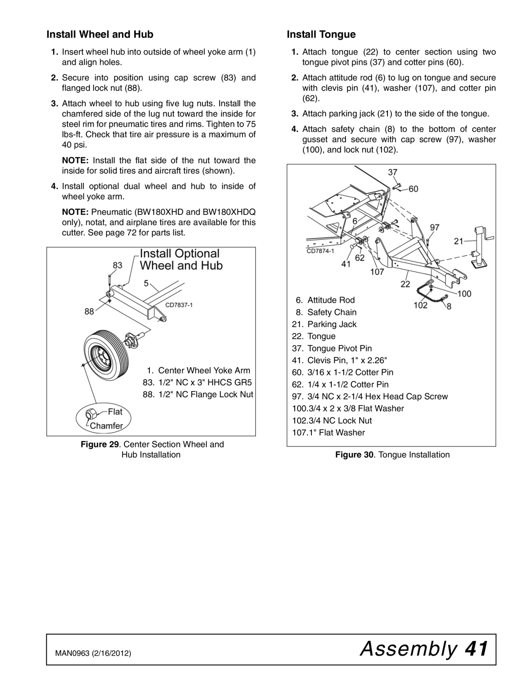
4.Install optional dual wheel and hub to inside of wheel yoke arm.
NOTE: Pneumatic (BW180XHD and BW180XHDQ only), notat, and airplane tires are available for this cutter. See page 72 for parts list.
1.Center Wheel Yoke Arm
83. 1/2" NC x 3" HHCS GR5
88. 1/2" NC Flange Lock Nut
Figure 29. Center Section Wheel and
Hub Installation
Install Tongue
1.Attach tongue (22) to center section using two tongue pivot pins (37) and cotter pins (60).
2.Attach attitude rod (6) to lug on tongue and secure with clevis pin (41), washer (107), and cotter pin (62).
3.Attach parking jack (21) to the side of the tongue.
4.Attach safety chain (8) to the bottom of center gusset and secure with cap screw (97), washer (100), and lock nut (102).
6.Attitude Rod
8.Safety Chain
21.Parking Jack
22.Tongue
37.Tongue Pivot Pin
41.Clevis Pin, 1" x 2.26"
60.3/16 x
62.1/4 x
97.3/4 NC x
102.3/4 NC Lock Nut 107.1" Flat Washer
Figure 30. Tongue Installation
MAN0963 (2/16/2012) | Assembly 41 |
|
|