Delta Electronics DVP01PU-S specifications 注意事項, 產品簡介, 所組成。, Introduction, Specifications, Others

Models: DVP01PU-S

1 2
Download 2 pages 59.01 Kb
Page 1
Image 1
￿Introduction

Warning

ENGLISH

￿This Instruction Sheet only provides descriptions for installation, wiring and trial run. For further infromation, please refer to special module of PLC Application Manual.

￿DO NOT touch terminals when power on. Please must power OFF before wiring.

￿This is an OPEN TYPE PLC. The PLC should be kept in an enclosure away from airborne dust, humidity, electric shock risk and vibration. Also, it is equipped with protective methods such as some special tools or keys to open the enclosure in order to prevent hazard to users or damage the PLC.

￿DO NOT connect the AC input power to any of the input/output terminals, or it may damage the PLC. Check all the wiring prior to power up.

￿Introduction

￿Model Explanation & and Peripherals

DVP01PU-S (positioning unit) is mainly applied to the speed/position control of step/servo driven system. The maximum output pulse can be up to 200 kPPS, and built-in various route control modes. The DVP-PLC SS/SA/SC/SX/SV series can read/write DVP01PU-S via FROM/TO instrucitons. There are 49 CRs (Control Register) with 16-bit for each register in DVP01PU-S. The 32-bits data is composed of 2 continuous CR number.

Description

Terminal name


Content


Response


CR No.


START

Start input terminal


4ms/12ms


Address

Latched

Attribute

Content


Setting Range


STOP

Stop input terminal


4ms

HM LW


LSP/LSN

Limit Stroke of right/left limit


1ms


ΦA+, ΦA-

A-phase terminal (+, -) of manual pulse generator input (line driver input)

200kHz

#22 H’41A6


R/W

Deceleration time

Range: 10 ~ +32,767 ms

factory setting: 100 ms


Tdec


ΦB+, ΦB-

B-phase terminal (+, -) of manual pulse generator input (line driver input)

200kHz


Input


Target

Range: -2,147,483,648 ~ +2,147,483,647 unit*1 (-2,147,483,648 ~


PG0+, PG0-

Zero signal input terminal +, - (line driver input)


4ms

#24 #23

H’41A7


R/W


position (I) P(I)

+2,147,483,647 pulse transfer value) *2; factory setting: 0 unit*1


Offers two different functions depending on operation mode.


Running

Range: -2,147,483,648 ~ +2,147,483,647 unit*1 (10 ~ 200 kPPS pulse


DOG

(1) It is near-point signal in zero return mode.


1ms

#26 #25 H’41A9


R/W


speed (I) V(I)

transfer value) *2; factory setting: 1,000 unit*1


(2) It is start signal on interrupt 1st or interrupt 2nd speed mode.


Target


S/S

Signal common terminal of these Inputs (START, STOP, DOG, LSP, LSN)

-


Range: -2,147,483,648 ~ +2,147,483,647 unit*1 (-2,147,483,648 ~


#28 #27 H’41AB


R/W

position (II)


+2,147,483,647 pulse transfer value) *2, factory setting: 0 unit*1


CLR+, CLR-

Clear signal (clear signal of internal error counter for Servo drive)

4ms


P(II)


FP+, FP-

FP/RP mode: CW pulse output


I/O mode: Output pulse

200kHz


Running

Range: 0 ~ +2,147,483,647 unit*1 (10 ~ 200 kPPS pulse transfer value) *2

Output

AB-phase mode: A-phase output


#30 #29 H’41AD


R/W


speed (II) V(II)

Factory setting: 2,000 unit*1


RP+, RP-

FP/RP mode: CCW pulse output


I/O mode: direction output

200kHz


b15 b14 b13

b12

b11

b10

b9

b8

b7

b6

b5

b4

b3

b2

b1

b0


AB-phase mode: B-phase output


Running


CLR output (On/Off) CLR signal output mode
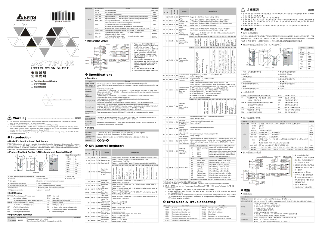


￿ Input/Output Circuit


instruction


0


Software START ABS/REL Coordinate

Zero return start


CCW pulse STOP

CW pulse


Software STOP

Error reset


#31 H’41AF

R/W


=


factory setting:

-

-

-

Current


position

-

JOG-

JOG+

STOP


D VP0 1 PU -S

+24 V DC IN

D elt a S ervo

1. Please use 22-16AWG (1.5mm)


H’0000


ASD A se ries


wiring (either single or multiple core)


S TART


2 4V

VD D 1 7

24V


for I/O wiring terminals. PLC


b15 b14

b13

b12

b11~b9

b8

b7

b6

b5

b4

b3

b2

b1

b0


STO P


0V

C O M+ 11


terminal screws should be tightened


Manual pulse generator range limitation


Manual pulse generator input operation


L SP


to 1.95 kg-cm (1.7in-lbs). Use


start


start


L SN


F P+

/P LS

4 3


Variable speed operation mode start


copper conductors only, 60/75oC.


D OG


F P-

P LS

4 1


position mode


mode


S/S


RP +

S IG N 3 7


2.

DO NOT arrange the wiring of I/O


+ 2 4V


RP -

/S IG N 3 6


signal wires or power supply in the


start

start


M a nu al p uls e ge n era to r


same wiring duct.


position

S hie ld ed c ab le


Work mode


A-p has e


A+


C LR+

D I2

1 0


3.

Make sure the terminals

of

#32 H’41B0

R/W

Factory setting:


A-


C LR -

C O M- 4 5


power module and DVP01PU-S are


H’0001


B+


5-2 4V D C


properly grounded or connected to


setting


-speed

positionmode

-speed

positionmode


B-p ha s e


ΦB-


the cover of power distribution


unit


5-2 4 VD C


cabinet.


nd

st


P G 0+


4.

DO NOT wire to null terminal .


-

-

Currentposition:currentCR34,33;

speed:displayCR36,unit:35;￿0 pulse, 1 ￿

Returnfactoryto


MASKsetting


LSP/LSNmodestop

STOPmode

Interrupt 2

-speed

Interrupt 1

-speed


PG 0 -


5.

Use only 60/75°C copper conductors.


nd


st

￿ Specifications


2

1


#34 #33 H’41B1


R/W

Current position

Range display: -2,147,483,648 ~ +2,147,483,647 PLS


CP (PLS)

Factory setting: 0 PLS


￿ Functions


#36 #35 H’41B3


R/W

Current speed

Range display: 0 ~ +2,147,483,647 PPS


Item


Content


CS (PPS)

Factory setting: 0 PPS


Power supply


24V DC (-15% ~ +20%); Current consumption 70±10mA; Startup peak current 1.3 A


RS-485 communication address setting: setting range 01 ~ 254


Factory setting: K1. Baud rate setting: 4,800, 9,600, 19,200, 38,400, 57,600,

Max. number of

8 units; (SS/SA/SX/SC/SV series MPU can connect up to 8 extension modules without occupying any


and 115,200 bps. ASCII mode data format is 7Bit, even bit and 1 stop bit (7 E

connected axes

I/O)


Communication

1). RTU mode data format is 8Bit, even bit and 1 stop bit (8 E 1)


Distance value is set by CR


Distance


#37 H’41B5

R/W

address and

b0: 4,800 bps (bit/sec.),

b1: 9,600 bps (bit/sec.) (factory setting)


1. Setting range: -2,147,483,648 ~ +2,147,483,647;


-4

inch, Pulse;


instruction


2. Selectable unit: um, mdeg, 10


Baud rate

b2: 19,200 bps (bit/sec.),


b3: 38,400 bps (bit/sec.)


3. Selectable rate: 100, 101, 102, 103;

4. Selectable position: absolute and relative position instruction


Speed value is set by CR


setting

b4: 57,600 bps (bit/sec.),


b5: 115,200 bps (bit/sec.)


Speed


1. Setting range: -2,147,483,648 ~ +2,147,483,647 (conversion value of 10 ~ 200 kPPS pulse)


b6: reserved, b7: 0 for RTU, 1 for ASCII mode,


instruction


2. Selectable unit: pulse/s, cm/min, 10deg/min, inch/min


b8 ~ b15: communication address


Photo coupler is for insulation and there are LED indications for all output/input signals


b15 b14 b13 b12 b11 b10

b9

b8

b7

b6

b5

b4

b3

b2

b1

b0

External output

Outputs: FP and RP (line driver output 5V)


MPG input downward


Output: CLR is the type of NPN open collector transistor output (5 ~ 24V DC, less than 20mA)


Execution


MPG input upward


Position completed indication

Error occurred flag

CP value overflow

Zero return is done


Photo coupler is for insulation and there are LED indications for all output/input signals.


Status indication


status


Route paused indication


Input point: START, STOP, LSP, LSN, DOG(contact or open collector transistor, 24V DC±10%, 5±1mA)

#38 H’41B6


R/W


CCW pulse is


External input


factory setting:

-

-

-

-

-


-


CW pulse is outputting


Inputs: ΦA, ΦB (line driver or open collector transistor, 5 ~ 24V DC, 6 ~15mA)


H’XXXX


outputting


Input: PG0 (line driver or open collector transistor, 5 ~ 24V DC, 6 ~ 15mA)


Pulse output


Three selectable modes: Pulse/Dir, FP (CW)/RP (CCW), A/B (all modes are line driver output).


format


Position


CR data can be read/write via FROM/TO intruction of PLC MPU. The 32-bit data is composed of 2

#39 H’41B7


R

Error code

Please refer to “Error Code & Troubleshooting” for detail.


program & data


Factory setting: H’0000


continuous CR number. The range of 16-bit CR is CR#0 ~ CR#48.


transmission


Electronic


Please refer to the following explanation


Connect to


Modules are numbered from 0 ~ 7 with 0 closet and 7 farthest to the MPU. Up to 8 modules can be

#40 H’41B8


R/W

gearing number


DVP-PLC


of MPG input

Factory setting: H’1


connected without occupying any digital I/O.


series


Electronic


￿ Others


#41 H’41B9


R/W

gearing

Please refer to the following explanation


denominator of

Factory setting: H’1


Environmental specifications


MPG input


Operation


1. Operation: 0°C~ 55°C (Temperature), 50 ~ 95% (Humidity), pollution degree 2


Input frequency

The input frequency of manual pulse generator


/Storage


2. Storage: -25°C~ 70°C (Temperature), 5 ~ 95%

Humidity


#43 #42 H’41BA


R/W

of manual


Factory setting: 0


Vibration /Shock


pulse generator


Standard: IEC 61131-2, IEC 68-2-6 (TEST Fc)/IEC 61131-2 & IEC 68-2-27 (TEST Ea)


immunity


Accumulated

The count value of CW manual pulse input is “ +” symbol, on the contrary, the

Approvals


#45 #44 H’41BC


R/W

pulse input no.

CCW manual pulse input is “-“symbol. And the count value is nothing to do


of manual

with the ratio setting of manual electronic gearing (CR#40, #41).

Factory

￿ CR (Control Register)


pulse generator

setting: 0.


Value

Response speed


When response speed setting is faster, the


5

4ms (factory setting)


instructions of pulse output and manual


Response


CR No.


pulse generator input will be more


speed of


4


32ms


#46 H’41BE

R/W


synchronous. When response speed setting


注意事項


￿


DVP01PU-S


DVP-PLC

￿


￿


(Open Type)


/


(

:


)


衝擊意

￿


體,造成危險及損壞。


/


防止非維護人員操作或意外衝擊

￿


￿


DVP01PU-S


200 kPPS


DVP-PLC SS/SA/SX/SC/SV


FROM/TO


脈波輸出,內建


49


CR


16


32


CR來讀寫模組內之資料 模組

￿


0


1


3.0


4


6


25.20


5


60.00


3.40


S/S

A-


7


15


START

B+


8


10


11


14


STOP

B-


2


90.00


16


12


DOG

CLR+


9


定位模組安裝、配線回路及試機之參考,有關進一步的使用說明,請參考LSP

CLR-


手冊主要提-01PU


DVP


3


13


LSN

FP+


應用技3術手冊【特殊模組篇】


請勿在上


時觸摸任何端子。實施配線,務必關閉電源。


PG0+

FP-


3.00


機殼,因此使用者使用本機時,必須將之安裝於具防塵、防潮及免於電擊


機為開放型


PG0-

RP+


外之外殼配線箱內。另必須具備保護措施 如mm特殊之工具或鑰匙才可打開


A+

RP-


1.

交流輸入電源不可連接於輸入 出信號端,否則將造成嚴重的損壞,請在上電之前再次確認電源配線。


產品簡介


9.


/


2.


10. DIN


(35mm)


11. RS-485


3. DIN


4.

說明及週邊裝置


12.


/


5.


脈波產生單元主要可應用于步進或伺服驅動系統之速度或位置控制,最高13.


6.


/


14.


/


多種行程控制模式。透過


系列主機程式以指令


7.


暫存器,每個暫存器為

位。


15.


所組成。


內具有


位 數值參數由兩個連續編號的


8.


/


16.


￿

產品外觀與各部介紹指示燈、端子台


上排端子 下排端子


POWER


+5V


START


LV


STOP


19.5V


DOG


ERROR


On/Off


CR#39


FP


尺寸單位:


RP


LSP


ΦA


A


LSN


ΦB


B


PG0


CLR


電源、低電壓及運行指示燈


軌糟


￿


機種型號


軌固定扣


通訊口


+24V, 0V,


24V DC (-15 ~ +20%)


70±10mA


1.3 A


-


端子指示燈


START


固定槽


4ms/12ms


電源輸入口


STOP


4ms


擴充機 擴充模組連接口


定位孔


1ms


銘牌


LSP/LSN


ΦA+, ΦA-


A


+, -


200kHz


擴充機 擴充模組ΦB+,

連接口ΦB-


B


+, -


下排端子


200kHz


PG0+, PG0-


+, -


4ms


面板指示燈


2


1.


2.


DOG


依照運行模式不同有下列


1ms


電源


,內部


電源正常


啟動


一段速或二段速


S/S


(START, STOP, DOG, LSP, LSN)

停止輸入指示燈


-


低電壓指示燈,外部電源輸入小於


CLR+, CLR-


Servo


近點


4ms


,該指示燈亮


FP+, FP-


/


閃爍),當


/


AB


A

200kHz


指示燈(

/


/


AB


B

200kHz


RP+, RP-


反轉方向


錯誤編


不為零時動作


相輸入指示燈


右左極限輸入指示燈


手搖輪


:零點信號輸入指示燈


:清除信號輸出指示燈


種 類


端子

信號


回應特性


輸入電源,


,開機電流


電源


供應


,消耗電流


啟動


輸入


￿Product Profile & Outline (LED Indicator and Terminal Block)


0 0


4

6


Upper Row

1

3

2 5 .2 0

5

6 0 .0 0


3 .40

S/S


7


1 5


START


8

11

1 4


STOP

2


1 0


90.00


1 6


1 2


DOG


01PU-DVP

3


9


LSP


1 3


3


LSN

3.00


PG0+


Unit: mm


PG0-


A+


Lower Row A-

B+

B-

CLR+

CLR-

FP+

FP-

RP+

RP-


HM


LW


Address

Latched


Attribute

Content


Setting Range


manual pulse

3


108ms

is slower, the instruction of pulse output is


generator

2


256ms


slower than the instruction of manual pulse


#0


H’4190


R

Model No.

System setting, Read-only (The model number of DVP01PU-S is H’0110.)


1 or 0


500ms

generator input. Factory setting: 5


#2


#1


H’4191


R/W

Pulse rate (A)

Range: 1 ~ +2,147,483,647 PPS/REV, factory setting: 2,000


bit #


Status

Description


Pulse/Revolution (PLS/REV)


b0

START input

When START input is On, b0 is On.


b1

STOP input

When STOP input is On, b1 is On.


#4


#3


H’4193


R/W

Feed rate (B)

Range: 1 ~ +2,147,483,647 unit/REV, factory setting: 1,000 (unit*1/REV)


b15

b14

b13

b12

b11

b10

b9

b8

b7

b6

b5

b4

b3

b2

b1

b0


b2

DOG input

When DOG input is On, b2 is On.


input polarity

input polarity


Acceleration curve


return direction


output format

rate setting


#47

H’41BF


R

Terminal status

b3

PG0 input

When PG0 input is On, b3 is On.


Parameter

response


trigger time

direction

input polarity

input polarity


b4

LSP input

When LSP input is On, b4 is On.


#5


H’4195


R/W

setting

polarity


b5

LSN input

When LSN input is On, b5 is On.


Factory setting:


setting


b6

A phase input

When A phase input is On, b6 is On.


H’0000


b7

B phase input

When B phase input is On, b7 is On.


￿


/


1.


/


DVP01PU-S


+24VDC


22-16AWG入配線端(1.5mm)請使用


START


24V

輸入

VDD 17

24V


PLC

單蕊祼線


STOP

停止


0V


COM+ 11


1.95 kg-cm (1.7lb端子鏍絲扭力-in)


LSP


LSN


FP+


/PLS 43


2.


DOG


FP-


PLS 41


S/S


RP+


SIGN 37


+24V


RP-


/SIGN 36


與在輸配出線點時或請電勿源將等輸動入力點

線信置號於


A+


CLR+


DI2 10


3.


A

手搖輪脈波

隔離線

Φ


CLR-


COM台達-ASDA45伺服驅系動列器


DVP01PU-S

端及


A-


右極限輸入左極限輸入


手搖輪

相輸入

(差動信號輸入)


零點


輸入


(差動信號 入)


插 啟動信號


種變化: 原點復歸時為近點信號。


信號共用端


輸入點


清除信號(

驅動器內部偏差計數器清除信號)


脈波


相模式: 相輸出


正 反轉模式:反轉方向脈波輸出;脈波 方向:方向輸出端;


1.

Status Indicator (Power, LV and ERROR)

2.

Model name

3.

DIN rail clip

4. Terminal

5.

Terminal indicator

6.

Mounting hole

7.

Nameplate

8.

Extension port to connect extension module


9.

Extension unit/module clip

10.

DIN rail track (35mm)


11. RS-485 communication port

12.

Clip for combining extension modules


13.

Power input

14.

Extension port to connect extension module


15.

Upper row terminals

16.

Lower row terminals


￿LED Display

POW ER

: Power indicator, +5V internal power

START : Start input

LV

: Low voltage indicator

STOP

: Stop input


lit when external input power is lower than 19.5V

DOG

: DOG (near point signal) input

ERROR

: Error indicator (ON/OFF blinking).

FP

: CW pulse output


It will blink when CR#39 is not 0.

RP

: CCW pulse output

LSP

: Right limit input indicator

ΦA

: A-phase input of manual pulse generator

LSN

: Left limit input indicator

ΦB

: B-phase input of manual pulse generator

PG0

: Zero signal input indicator

CLR

: Output clear signal

￿Input/Output Terminal

Description

Terminal name

Content

Response

Power supply

+24V, 0V

Power input/24V DC (-15 ~ +20%)

-

Current consumption 70 10mA; Startup peak current 1.3 A


STOP

START

START time

options

DOG

DOG

Pulse

Zero

LSN

LSP

Pulse

Position

Unit


b8

CLR output

When CLR output is On, b8 is On.


#48 H’41C0

R System version System version is in hexadecimal. e.g. software V1.00 is for H’0100.

#7

#6

H’4196

R/W

Maximum

Range: 0 ~ +2,147,483,647 unit*1 (10 ~ 200 kPPS) *2


speed Vmax

Factory setting: 200,000 unit*1


*1: Unit setting varies based on b0 and b1 setting of CR#5.


Bias speed

Range: 0 ~ +2,147,483,647 unit*1 (0 ~ 200 kPPS pulse transfer value) *2

*2: Use max. Pulse output if upper limit is exceeded. Use min. pulse output if lower limit is exceeded.

#9

#8

H’4198

R/W


Vbias

Factory setting: 0 unit*1


CR#0 ~ CR48: user can use the corresponding addresses H’4190 ~ 41C0 to read/write data via RS-485

#11 #10 H’419A

R/W

JOG speed

Range: 0 ~ +2,147,483,647 unit*1 (10 ~ 200 kPPS pulse transfer value) *2


communication.


VJOG

Factory setting: 5,000 unit*1


1.

Baud rate supportive: 4,800, 9,600, 38,400, 57,600, and 115,200 bps.


Zero return

Range: 0 ~ +2,147,483,647 unit*1 (10 ~ 200 kPPS pulse transfer value) *2


2.

Modbus ASCII/RTU: ASCII mode is 7 bits, even bit and 1 stop bit (7, E, 1). RTU mode is 8 bits, even bit

#13 #12 H’419C

R/W


and 1 stop bit (8, E, 1).


speed VRT

Factory setting: 50,000 unit*1


3.


Zero return


Function code: 03’H for read data from CR; 06’H for write one word in CR; 10’H for write many words in


Range: 0 ~ +2,147,483,647 unit*1 (10 ~ 200 kPPS pulse transfer value) *2


CR. It indicates DVP01PU-S hardware malfunction or error parameter setting when error LED flashes.

#15 #14 H’419E

R/W

deceleration


Factory setting: 1,000 unit*1


ERR code is recorded in CR#39.


speed VCR


The number of

Range: 0 ~ +32,767 PLS


￿ Error Code & Troubleshooting


#16

H’41A0

R/W

PG0 in zero


Factory setting: 0 PLS


return mode N


The number of


Error code


Description


Error code

Description


Range: -32,768 ~ +32,767 PLS


#17

H’41A1

R/W

pulse in zero


H’0000

No error


H’0014

JOG speed (VJOG) setting error


return mode P

Factory setting: 0 PLS


H’0001

Target position (I) setting error


H’0020

CW pulse is forbidden


Zero return

b0: zero return mode,


H’0002

Target address (II) setting error


H’0021

CCW pulse is forbidden


#18

H’41A2

R/W

mode H Mode

b1: detect DOG falling-edge in zero return mode


H’0010

Running

speed (I) setting error


H’0030

Low voltage

#20 #19 H’41A3

R/W

Zero point

Range: 0 ~ 999,999 unit*1


H’0011

Running speed (II) setting error


H’0080

Hardware error in internal memory


setting (HP)

Factory setting: 0 unit*1


H’0012

Zero return deceleration (VCR) setting error

H’0081

Data write in error in internal memory


Acceleration


#21 H’41A5

R/W

Range: 10 ~ +32,767 ms


H’0013 Zero return (VRT) setting error


time Tacc

Factory setting: 100 ms


±


B


B+

(-15% ~ +20%)


5-24VDC


B-


5-24VDC


PG0+


將系端統連接接點到作系第統三接種地接點地,或再接


PG0-


4.


規格


5.


60/75°C


￿


￿


入 輸出回路配24V DC


70 ±10mA

1.3 A

輸出


( )

8

I/O

SS/SA/SX/SC/SV


8


(CR)


或多蕊線。


1.

-2,147,483,648 ~ +2,147,483,647


2.距離設定值由控制um,暫存mdeg,10-4 inch, Pulse


3.

100, 101, 102, 103


糟內。


4.


1.速度


(CR)


-2,147,483,648 ~ +2,147,483,647 (10 ~ 200kPPS

)


2.

Pulse/s, cm/min, 10deg/min, inch/min


同一


/

LED


請將 源模組之


全部採用光耦合作隔離FP, RP

輸出

5V


定位控制模組之


CLR

NPN

5 ~ 24V DC, 20mA


到配電箱之機殼上。


外部速距最電度離大源功連輸值項能出點接台入 規軸格數


輸出點:台可單設(選位定軸擇可值);選:對位占輸出差動驅置或相對移動量任何,消點耗數電信號入,流來設定,;信號皆附;;開機作為信號及系電列流主機所能連接特殊擴充機台數總和為脈波只空示能端使用子 請勿配線的。銅導線。台)

Page 1
Image 1
Delta Electronics DVP01PU-S specifications 注意事項, 產品簡介, 所組成。, Introduction, Specifications, CR Control Register, Functions