module and is thus not required on the host board. The voltage swing on these lines will be between 370 and 2000 mV differential (185 – 1000 mV single ended) when properly terminated.
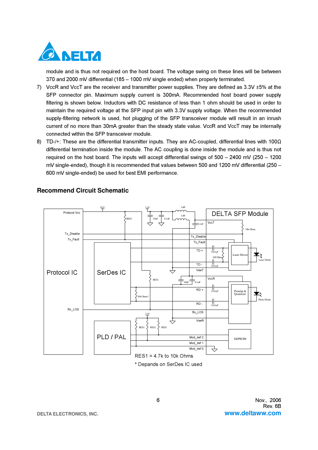
7)VccR and VccT are the receiver and transmitter power supplies. They are defined as 3.3V ±5% at the SFP connector pin. Maximum supply current is 300mA. Recommended host board power supply filtering is shown below. Inductors with DC resistance of less than 1 ohm should be used in order to maintain the required voltage at the SFP input pin with 3.3V supply voltage. When the recommended
8)
Recommend Circuit Schematic
VCC | 3.3V | 1uH |
Protocol Vcc
RES1
Tx_Disable
Tx_Fault
Protocol IC | SerDes IC |
1uH | DELTA SFP Module |
10uF 0.1uF
0.1uF VccT
10k Ohms
Tx_Disable
Tx_Fault |
|
TD + | 0.01uF |
| Laser Driver |
| 100 Ohms |
| Laser Diode |
TD - | 0.01uF |
| |
VeeT |
|
RES1 | 0.1uF | VccR |
10uF |
| |
| RD + | 0.01uF |
|
|
100 Ohms*
RD - 0.01uF
Rx_LOS
3.3V | Rx_LOS |
| |
| VeeR |
RES1 RES1 RES1 |
|
Preamp &
Quantizer
Photo Diode
PLD / PAL
Mod_def 2
Mod_def 1
Mod_def 0
EEPROM
RES1 = 4.7k to 10k Ohms
* Depands on SerDes IC used
6 | Nov., 2006 |
| Rev. 6B |
DELTA ELECTRONICS, INC. | www.deltaww.com |