|
|
|
|
|
|
| Preliminary | ||
|
|
|
|
|
|
|
| ||
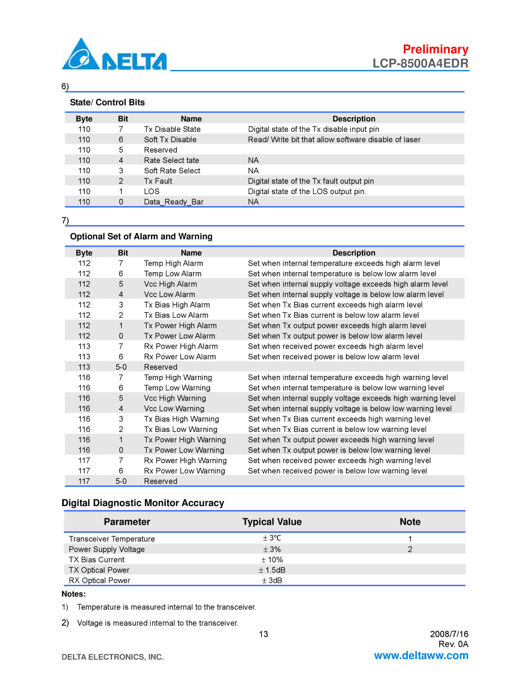
6) |
|
|
|
|
|
|
|
| |
|
| State/ Control Bits |
|
|
| ||||
|
|
|
|
|
|
|
|
|
|
|
| Byte |
| Bit |
| Name | Description |
| |
110 | 7 | Tx Disable State | Digital state of the Tx disable input pin | ||||||
|
| 110 |
| 6 | Soft Tx Disable | Read/ Write bit that allow software disable of laser |
| ||
110 | 5 | Reserved |
|
|
| ||||
|
| 110 |
| 4 | Rate Select tate | NA |
| ||
110 | 3 | Soft Rate Select | NA | ||||||
|
| 110 |
| 2 | Tx Fault | Digital state of the Tx fault output pin |
| ||
110 | 1 | LOS | Digital state of the LOS output pin. | ||||||
|
| 110 |
| 0 | Data_Ready_Bar | NA |
|
| |
7) |
|
|
|
|
|
|
|
| |
|
| Optional Set of Alarm and Warning |
|
|
| ||||
|
|
|
|
|
|
|
|
| |
|
| Byte |
| Bit |
| Name | Description |
| |
112 | 7 | Temp High Alarm | Set when internal temperature exceeds high alarm level | ||||||
112 | 6 | Temp Low Alarm | Set when internal temperature is below low alarm level | ||||||
|
| 112 |
| 5 | Vcc High Alarm | Set when internal supply voltage exceeds high alarm level |
| ||
|
| 112 |
| 4 | Vcc Low Alarm | Set when internal supply voltage is below low alarm level |
|
| |
112 | 3 | Tx Bias High Alarm | Set when Tx Bias current exceeds high alarm level | ||||||
112 | 2 | Tx Bias Low Alarm | Set when Tx Bias current is below low alarm level | ||||||
|
| 112 |
| 1 | Tx Power High Alarm | Set when Tx output power exceeds high alarm level |
| ||
|
| 112 |
| 0 | Tx Power Low Alarm | Set when Tx output power is below low alarm level |
|
| |
113 | 7 | Rx Power High Alarm | Set when received power exceeds high alarm level | ||||||
113 | 6 | Rx Power Low Alarm | Set when received power is below low alarm level | ||||||
|
| 113 |
| Reserved |
|
|
| ||
116 | 7 | Temp High Warning | Set when internal temperature exceeds high warning level | ||||||
116 | 6 | Temp Low Warning | Set when internal temperature is below low warning level | ||||||
|
| 116 |
| 5 | Vcc High Warning | Set when internal supply voltage exceeds high warning level |
| ||
|
| 116 |
| 4 | Vcc Low Warning | Set when internal supply voltage is below low warning level |
|
| |
116 | 3 | Tx Bias High Warning | Set when Tx Bias current exceeds high warning level | ||||||
116 | 2 | Tx Bias Low Warning | Set when Tx Bias current is below low warning level | ||||||
|
| 116 |
| 1 | Tx Power High Warning | Set when Tx output power exceeds high warning level |
| ||
|
| 116 |
| 0 | Tx Power Low Warning | Set when Tx output power is below low warning level |
|
| |
117 | 7 | Rx Power High Warning | Set when received power exceeds high warning level | ||||||
117 | 6 | Rx Power Low Warning | Set when received power is below low warning level | ||||||
|
| 117 |
| Reserved |
|
|
| ||
Digital Diagnostic Monitor Accuracy
| Parameter | Typical Value |
| Note |
|
|
|
|
|
|
|
| Transceiver Temperature | ± 3℃ | 1 |
| |
| Power Supply Voltage | ± 3% |
| 2 |
|
| TX Bias Current | ± 10% |
|
|
|
| TX Optical Power | ± 1.5dB |
|
|
|
| RX Optical Power | ± 3dB |
|
|
|
Notes: |
|
|
|
| |
1) Temperature is measured internal to the transceiver. |
|
|
| ||
2) Voltage is measured internal to the transceiver. | 13 | 2008/7/16 | |||
|
| ||||
|
|
|
| Rev. 0A | |
DELTA ELECTRONICS, INC. |
|
| www.deltaww.com | ||