Note (1). Measured with Light source +1dBm, 1490nm, ER=9dB; BER
Note (2). When SD deasserted, the data output is
Note (4). Measured at wavelength of 1490nm.
5. Electrical Interface Characteristics
Parameter |
| Symbol | Min. | Typ. | Max. | Unit | Note |
Transmitter |
|
|
|
|
|
|
|
Total Supply Current |
| ICC |
|
| A | mA | Note (1) |
Differential line input Impedance |
| RIN | 80 | 100 | 120 | Ohm |
|
Differential Data Input Swing |
| VDT | 400 |
| 1600 | Note (2) | |
BiasCNT Input Voltage- High |
| VBCH | 2 |
| Vcc | V | LVTTL |
BiasCNT Input Voltage- Low |
| VBCL | 0 |
| 0.8 | V | |
|
|
| |||||
Receiver |
|
|
|
|
|
|
|
Total Supply Current |
| ICC |
|
| B | mA | Note (1) |
Differential Data Output Swing |
| VDR | 400 |
| 900 | Note (2) | |
Signal Detect Output |
| VLOSH | 2 |
| Vcc+0.3 | V | LVTTL |
Signal Detect Output |
| VLOSL | 0 |
| 0.8 | V | |
|
|
| |||||
Note (1). A (TX)+ B (RX) = 300mA | (Not include termination circuit) |
|
|
| |||
Note (2). Internally AC coupled, but requires a 100Ohm differential termination at or internal to Serializer/ Deserializer.
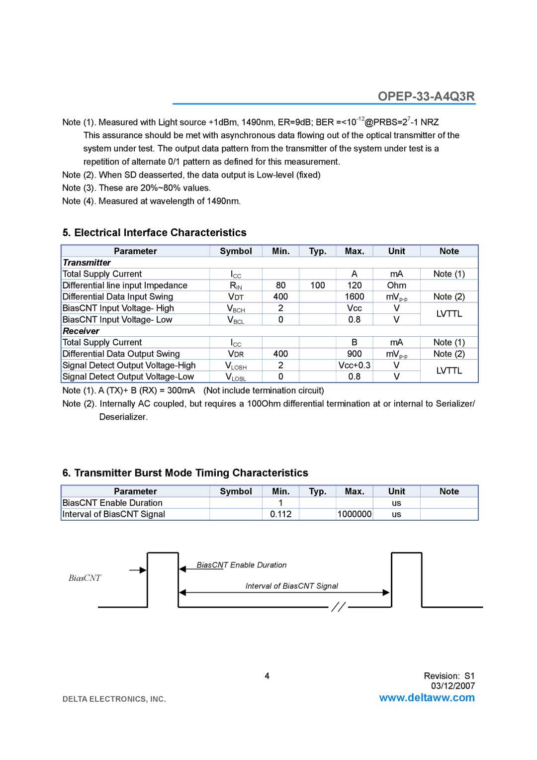
6. Transmitter Burst Mode Timing Characteristics
Parameter | Symbol | Min. | Typ. | Max. | Unit | Note |
BiasCNT Enable Duration |
| 1 |
|
| us |
|
Interval of BiasCNT Signal |
| 0.112 |
| 1000000 | us |
|
BiasCNT
BiasCNT Enable Duration
Interval of BiasCNT Signal
4 | Revision: S1 |
| 03/12/2007 |
DELTA ELECTRONICS, INC. | www.deltaww.com |