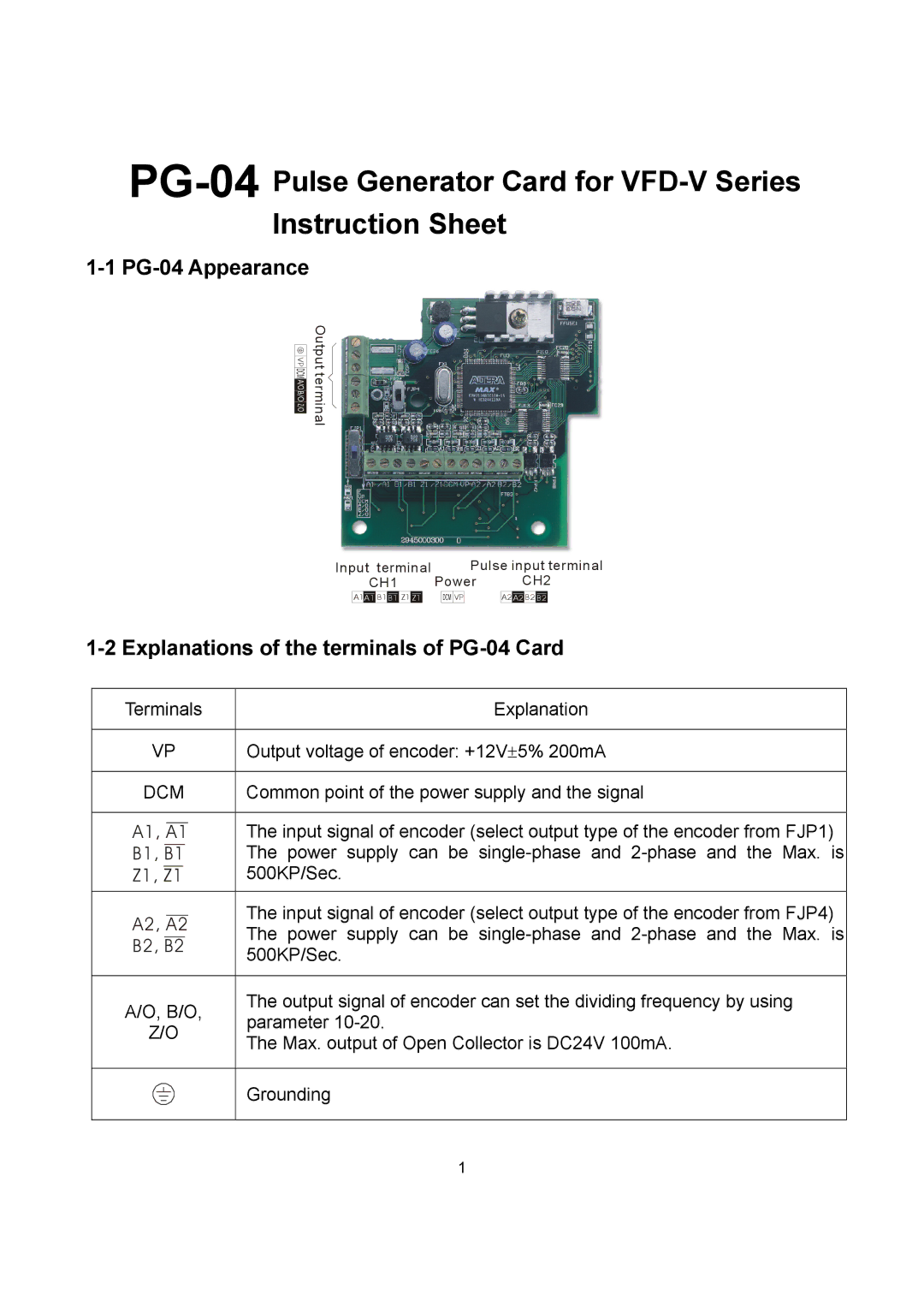
1-1 PG-04 Appearance
VP
Ou pt ut
et rm ni al
Input terminal | Pulse input terminal | |
CH1 | Power | CH2 |
A1A1 B1 B1 Z1 Z1
![]()
![]()
![]()
![]()
![]() VP
VP
A2 A2 B2 B2
1-2 Explanations of the terminals of PG-04 Card
Terminals
VP
DCM
A1,
B1,
Z1, Z1
A2, A2
B2, B2
A/O, B/O,
Z/O
Explanation
Output voltage of encoder: +12V±5% 200mA
Common point of the power supply and the signal
The input signal of encoder (select output type of the encoder from FJP1) The power supply can be
The input signal of encoder (select output type of the encoder from FJP4) The power supply can be
The output signal of encoder can set the dividing frequency by using parameter
The Max. output of Open Collector is DC24V 100mA.
Grounding
1