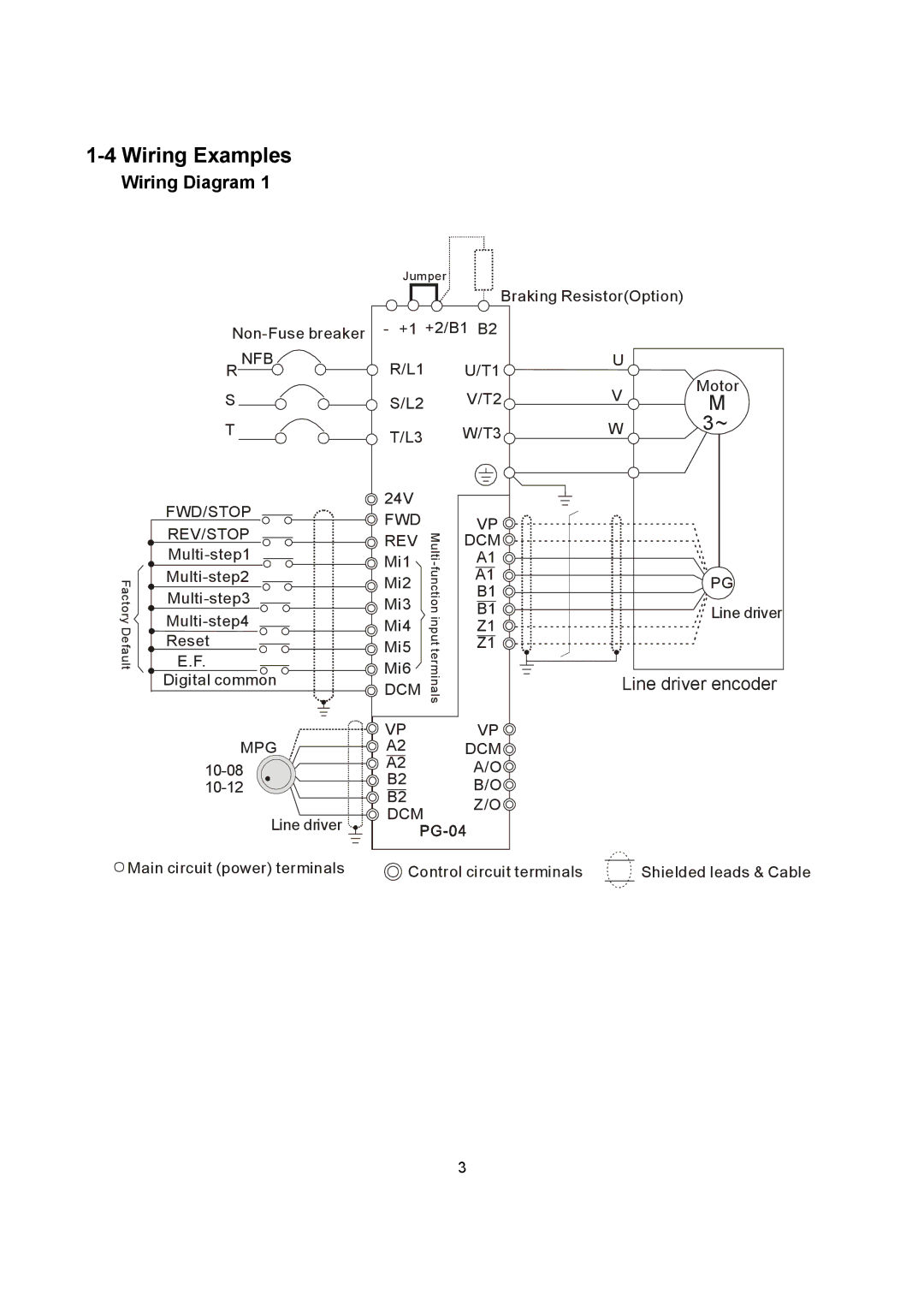
1-4 Wiring Examples
Wiring Diagram 1
Jumper
Braking Resistor(Option)
| - +1 +2/B1 B2 |
|
| |||
| R NFB | R/L1 |
| U/T1 | U | Motor |
|
|
|
|
| V | |
| S | S/L2 |
| V/T2 | M | |
| T | T/L3 |
| W/T3 | W | 3~ |
|
|
| ||||
| FWD/STOP | 24V |
|
|
|
|
| FWD |
| VP |
|
| |
| REV/STOP | Multi- |
|
| ||
| REV | DCM |
|
| ||
|
|
| ||||
| Mi1 | A1 |
|
| ||
Factory Default | Mi2 | function input terminals | A1 |
| PG | |
B1 |
| |||||
Mi3 |
|
| ||||
B1 |
| Line driver | ||||
| ||||||
Mi4 | Z1 |
|
| |||
Reset | Mi5 | Z1 |
|
| ||
E.F. | Mi6 |
|
|
| ||
Digital common |
| Line driver encoder | ||||
DCM |
| |||||
|
|
|
|
| ||
|
| VP |
| VP |
|
|
| MPG | A2 |
| DCM |
|
|
| A2 |
| A/O |
|
| |
| B2 |
| B/O |
|
| |
| B2 |
|
|
| ||
|
|
| Z/O |
|
| |
|
| DCM |
|
|
| |
| Line driver |
|
|
|
| |
|
|
|
|
|
| |
Main circuit (power) terminals | Control circuit terminals | Shielded leads & Cable |
3