ELECTRICAL CHARACTERISTICS CURVES
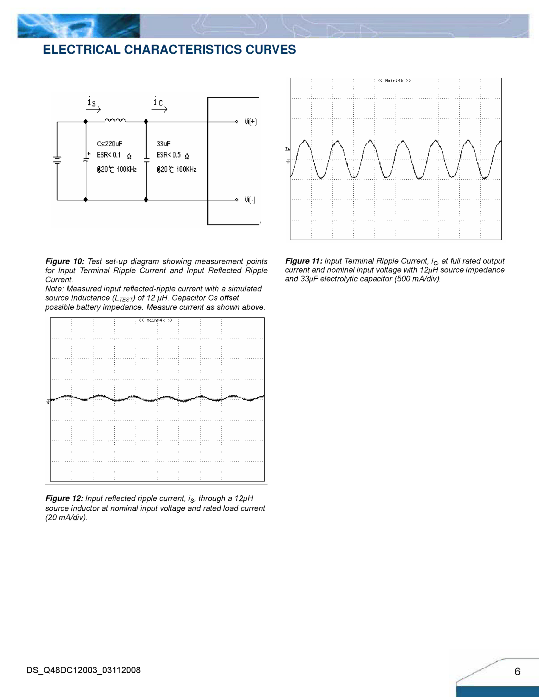
Figure 10: Test set-up diagram showing measurement points for Input Terminal Ripple Current and Input Reflected Ripple Current.
Note: Measured input
Figure 12: Input reflected ripple current, is, through a 12µH source inductor at nominal input voltage and rated load current (20 mA/div).
Figure 11: Input Terminal Ripple Current, ic, at full rated output current and nominal input voltage with 12µH source impedance and 33µF electrolytic capacitor (500 mA/div).
DS_Q48DC12003_03112008 | 6 |