ELECTRICAL CHARACTERISTICS CURVES
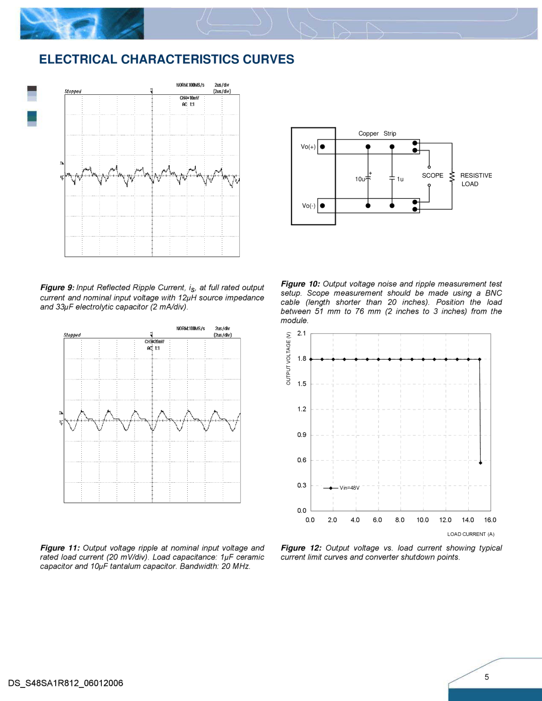
Copper | Strip |
|
|
Vo(+) |
|
|
|
10u | 1u | SCOPE | RESISTIVE |
| LOAD | ||
|
|
| |
|
|
|
Figure 9: Input Reflected Ripple Current, is, at full rated output current and nominal input voltage with 12µH source impedance and 33µF electrolytic capacitor (2 mA/div).
Figure 11: Output voltage ripple at nominal input voltage and
rated load current (20 mV/div). Load capacitance: 1µF ceramic
capacitor and 10µF tantalum capacitor. Bandwidth: 20 MHz.
Figure 10: Output voltage noise and ripple measurement test setup. Scope measurement should be made using a BNC cable (length shorter than 20 inches). Position the load between 51 mm to 76 mm (2 inches to 3 inches) from the module.
(V) | 2.1 |
|
|
|
|
|
|
|
|
VOLTAGEOUTPUT | 1.8 |
|
|
|
|
|
|
|
|
|
|
|
|
|
|
|
|
| |
| 1.5 |
|
|
|
|
|
|
|
|
| 1.2 |
|
|
|
|
|
|
|
|
| 0.9 |
|
|
|
|
|
|
|
|
| 0.6 |
|
|
|
|
|
|
|
|
| 0.3 |
| Vin=48V |
|
|
|
|
|
|
|
|
|
|
|
|
|
|
| |
| 0.0 |
|
|
|
|
|
|
|
|
| 0.0 | 2.0 | 4.0 | 6.0 | 8.0 | 10.0 | 12.0 | 14.0 | 16.0 |
LOAD CURRENT (A)
Figure 12: Output voltage vs. load current showing typical current limit curves and converter shutdown points.
DS_S48SA1R812_06012006
5