FEATURES DESCRIPTIONS (CON.)
Output Voltage Adjustment
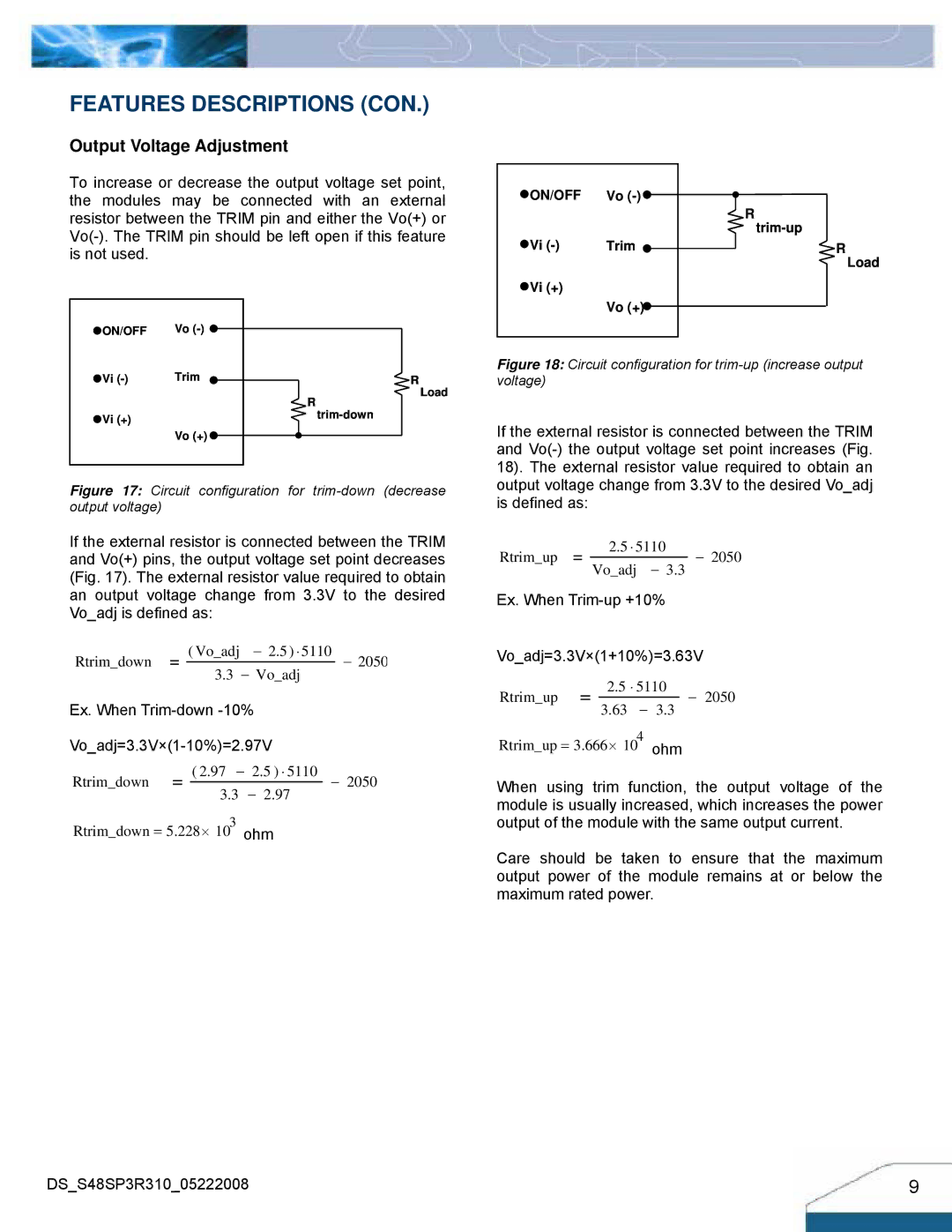
To increase or decrease the output voltage set point, the modules may be connected with an external resistor between the TRIM pin and either the Vo(+) or
![]() ON/OFF Vo
ON/OFF Vo ![]()
![]() Vi
Vi ![]()
![]() Vi (+)
Vi (+)
Vo (+)![]()
![]() R
R
![]() R
R
Load
![]() ON/OFF Vo
ON/OFF Vo ![]()
![]() Vi
Vi
![]() R
R
Figure 18: Circuit configuration for trim-up (increase output voltage)
![]() R
R
Load
![]() Vi (+)
Vi (+)
Vo (+) ![]()
If the external resistor is connected between the TRIM and
Figure 17: Circuit configuration for trim-down (decrease output voltage)
If the external resistor is connected between the TRIM and Vo(+) pins, the output voltage set point decreases (Fig. 17). The external resistor value required to obtain an output voltage change from 3.3V to the desired Vo_adj is defined as:
Rtrim_down |
|
|
|
| ( Vo_adj | − 2.5 ) ⋅ 5110 | − 2050 | |||
|
|
| 3.3 − Vo_adj |
|
| |||||
|
|
|
|
| ||||||
|
|
|
|
|
|
|
|
| ||
Ex. When |
|
|
| |||||||
|
|
| ||||||||
Rtrim_down |
|
|
| ( 2.97 − | 2.5 ) ⋅ 5110 | − | 2050 | |||
| 3.3 | − 2.97 | ||||||||
| ||||||||||
|
|
|
|
|
|
|
| |||
Rtrim_down = 5.228⋅ 103 ohm
DS_S48SP3R310_05222008
output voltage change from 3.3V to the desired Vo_adj is defined as:
Rtrim_up |
|
| 2.5 ⋅ 5110 | − 2050 |
|
| Vo_adj − 3.3 | ||
|
Ex. When
Vo_adj=3.3V×(1+10%)=3.63V
Rtrim_up |
|
| 2.5 ⋅ 5110 | − 2050 |
|
| 3.63 − 3.3 | ||
|
Rtrim_up = 3.666⋅ 104 ohm
When using trim function, the output voltage of the module is usually increased, which increases the power output of the module with the same output current.
Care should be taken to ensure that the maximum output power of the module remains at or below the maximum rated power.
9