OWNER’S MANUAL

INSTALLATION

Continued

For Built-In Installation

WARNING: A licensed elec- trician must connect the wiring harness to electrical supply fol- lowing all local codes. Electri- cian must provide a clamp on the box cover to secure the wir- ing. Wiring should be routed through the bushing in the hole on the outer casing of heater.

Follow instructions Removing Valve Cover Shield, page 11, then

1.Install a snap bushing found in hard- ware kit into one of the holes found on rear of valve cover shield. The other hole is for a strain relief clamp (not supplied) to secure incoming electrical supply.

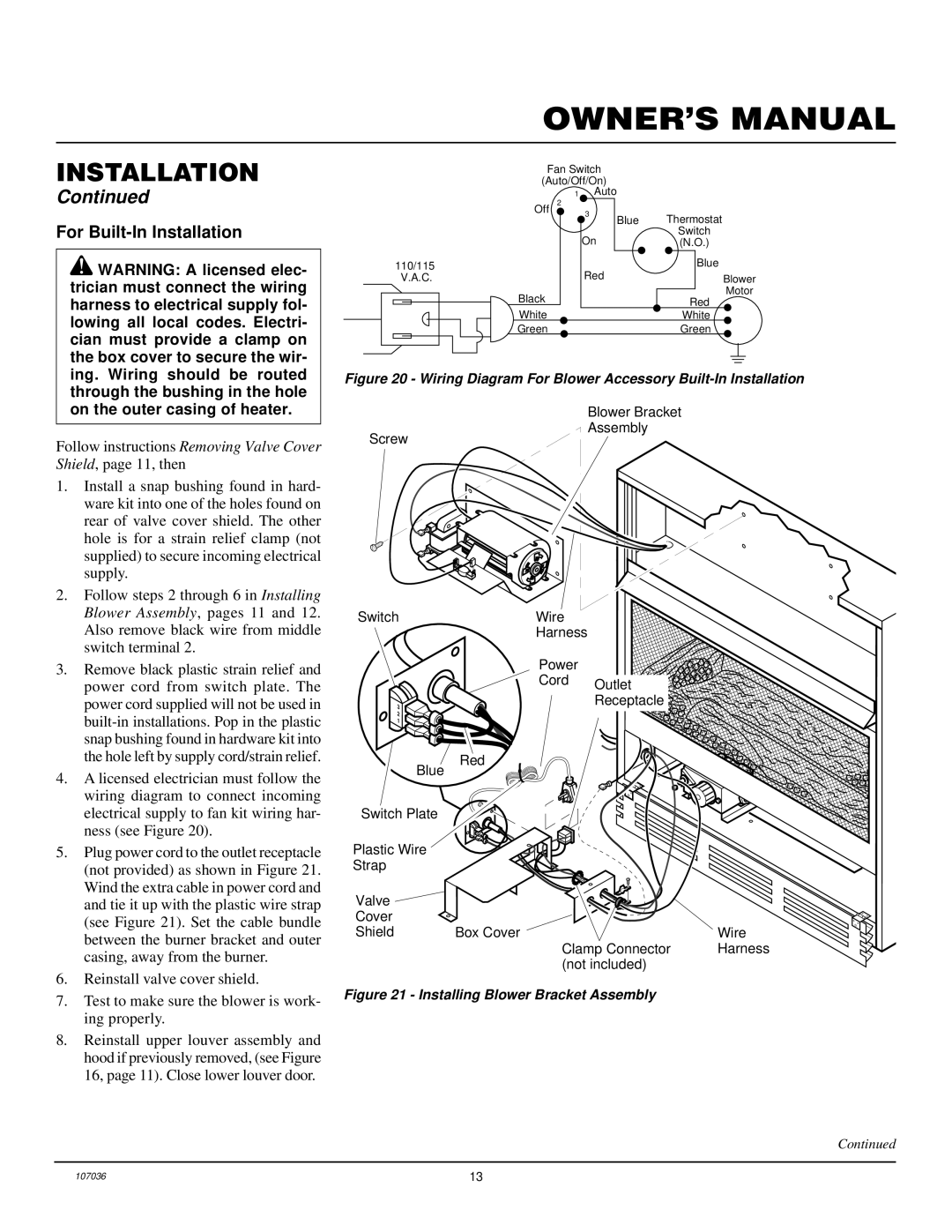
2.Follow steps 2 through 6 in Installing Blower Assembly, pages 11 and 12. Also remove black wire from middle switch terminal 2.

3.Remove black plastic strain relief and power cord from switch plate. The power cord supplied will not be used in built-in installations. Pop in the plastic snap bushing found in hardware kit into the hole left by supply cord/strain relief.

4.A licensed electrician must follow the wiring diagram to connect incoming electrical supply to fan kit wiring har- ness (see Figure 20).

5.Plug power cord to the outlet receptacle (not provided) as shown in Figure 21. Wind the extra cable in power cord and and tie it up with the plastic wire strap (see Figure 21). Set the cable bundle between the burner bracket and outer casing, away from the burner.

6.Reinstall valve cover shield.

7.Test to make sure the blower is work- ing properly.

8.Reinstall upper louver assembly and hood if previously removed, (see Figure 16, page 11). Close lower louver door.

Fan Switch

(Auto/Off/On)

1Auto


Off

2


3

Blue


Thermostat


On


Switch


(N.O.)

110/115


Red


Blue

V.A.C.


Blower


Black


Motor


Red


White


White


Green


Green

Figure 20 - Wiring Diagram For Blower Accessory Built-In Installation

Blower Bracket

Assembly

Screw

Switch


Wire


Harness


Power


Cord

Outlet


3


Receptacle


2


1


Blue

Red


Switch Plate


Plastic Wire


Strap


Valve


Cover


Shield

Box Cover


Wire


Clamp Connector

Harness


(not included)


Figure 21 - Installing Blower Bracket Assembly

Continued

107036

13

Page 13
Image 13
Desa CGCFTP 14, 000 to 26 For Built-In Installation, Wiring Diagram For Blower Accessory Built-In Installation

000 to 26, CGCFTP 14 specifications

Desa 000 to 26 and CGCFTP 14 represent advanced frameworks and protocols that are pushing the boundaries of digital communications and data transfer methodologies.

Desa 000 to 26 refers to a series of digital communication protocols designed to facilitate high-speed data transmission over diverse networks. These protocols have been tailored to accommodate a wide range of applications, from mobile communications to IoT devices. The primary characteristic of Desa 000 to 26 is its ability to support reliable and efficient data exchange, ensuring minimal latency and high bandwidth.

One of the main features of these protocols is adaptive bandwidth allocation, which allows the system to dynamically adjust the bandwidth based on real-time network conditions. This adaptability leads to optimal performance regardless of fluctuations in user demand or network congestion. Enhanced error correction techniques integrated into the Desa protocols also ensure data integrity during transmission, improving overall reliability.

On the other hand, CGCFTP 14 represents an evolution in file transfer protocols, specifically designed for secure and efficient data transfer between systems. This protocol leverages end-to-end encryption to safeguard data against unauthorized access during transfer. Key features of CGCFTP 14 include support for multi-threaded file transfers, which significantly accelerates the speed of large data transfers by concurrently sending multiple segments of a file.

CGCFTP 14 also incorporates advanced access control measures, allowing users to set permissions for file transfers. This characteristic is particularly valuable in corporate environments where data sensitivity is paramount. Furthermore, the protocol is compatible with various operating systems and platforms, providing ease of integration into existing systems, enhancing its versatility.

The combination of Desa 000 to 26 and CGCFTP 14 highlights the importance of robust, flexible, and secure communication methodologies in today’s digital landscape. These technologies cater to the ever-increasing demand for high-speed data transfer while ensuring security and reliability are not compromised. As businesses and individuals continue to rely on digital communication, the adoption of such innovations will undoubtedly shape the future of connectivity and data management.