OWNER’S MANUAL
VENTING INSTALLATION
Continued
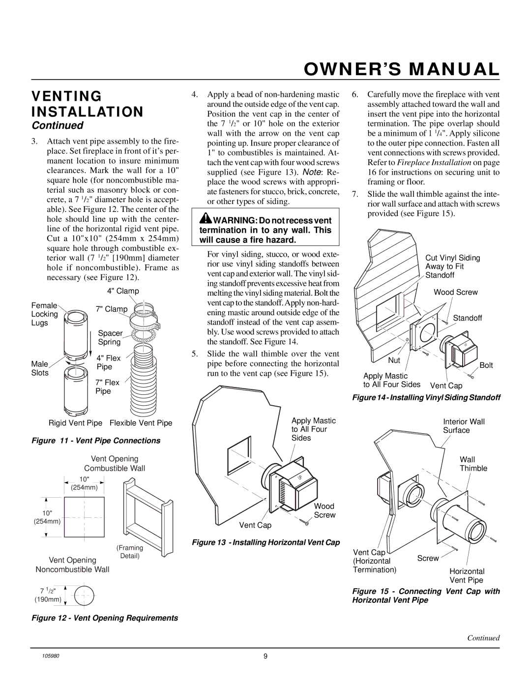
3.Attach vent pipe assembly to the fire- place. Set fireplace in front of it’s per- manent location to insure minimum clearances. Mark the wall for a 10" square hole (for noncombustible ma- terial such as masonry block or con- crete, a 7 1/2" diameter hole is accept- able). See Figure 12. The center of the hole should line up with the center- line of the horizontal rigid vent pipe. Cut a 10"x10" (254mm x 254mm) square hole through combustible ex- terior wall (7 1/2" [190mm] diameter hole if noncombustible). Frame as necessary (see Figure 12).
| 4" Clamp | |
Female | 7" Clamp | |
Locking | ||
| ||
Lugs |
| |
| Spacer | |
| Spring | |
Male | 4" Flex | |
Pipe | ||
Slots | ||
| ||
| 7" Flex | |
| Pipe | |
Rigid Vent Pipe Flexible Vent Pipe | ||
Figure 11 - Vent Pipe Connections
Vent Opening
Combustible Wall
10"
(254mm)
10"
(254mm)
(Framing
4.Apply a bead of
![]() WARNING: Do not recess vent termination in to any wall. This will cause a fire hazard.
WARNING: Do not recess vent termination in to any wall. This will cause a fire hazard.
For vinyl siding, stucco, or wood exte- rior use vinyl siding standoffs between vent cap and exterior wall. The vinyl sid- ing standoff prevents excessive heat from melting the vinyl siding material. Bolt the vent cap to the standoff. Apply
5.Slide the wall thimble over the vent pipe before connecting the horizontal run to the vent cap (see Figure 15).
Apply Mastic to All Four Sides
UP
Wood
Screw
Vent Cap
Figure 13 - Installing Horizontal Vent Cap
6.Carefully move the fireplace with vent assembly attached toward the wall and insert the vent pipe into the horizontal termination. The pipe overlap should be a minimum of 1 1/4". Apply silicone to the outer pipe connection. Fasten all vent connections with screws provided. Refer to Fireplace Installation on page 16 for instructions on securing unit to framing or floor.
7.Slide the wall thimble against the inte- rior wall surface and attach with screws provided (see Figure 15).
Cut Vinyl Siding
Away to Fit
Standoff
Wood Screw
Standoff
UP
Nut
Bolt
Apply Mastic
to All Four Sides Vent Cap
Figure 14 - Installing Vinyl Siding Standoff
Interior Wall
Surface
Wall
Thimble
Vent Cap
Vent Opening
Detail)
(Horizontal | Screw |
|
Noncombustible Wall
7 1/2" ![]() (190mm)
(190mm)
Figure 12 - Vent Opening Requirements
Termination) | Horizontal |
| Vent Pipe |
Figure 15 - Connecting Vent Cap with Horizontal Vent Pipe
Continued
105980 | 9 |