OWNER’S MANUAL

INSTALLATION

(Continued)

Providing Gas Piping to Furnace

You must provide gas piping from gas source to furnace. The gas piping must be in a vertical position where it connects to the furnace. This prevents interference with front cover installation.

Consult your local gas company for proper routing of the gas lines.

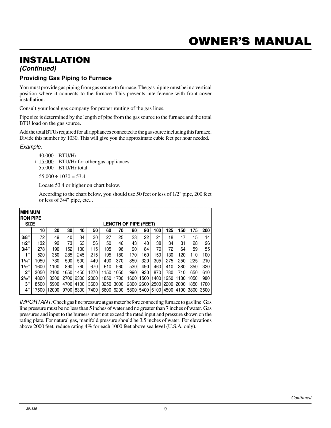
Pipe size is determined by the length of pipe from the gas source to the furnace and the total

BTU load on the gas source.

Add the total BTUs required for all appliances connected to the gas source including this furnace.

Divide this number by 1030. This will give you the approximate cubic feet per hour needed.

Example:

40,000 BTU/Hr

+15,000 BTU/Hr for other gas appliances

55,000 BTU/Hr total

55,000 ÷ 1030 = 53.4

Locate 53.4 or higher on chart below.

According to the chart below, you should use 50 feet or less of 1/2" pipe, 200 feet or less of 3/4" pipe, etc...

MINIMUM


IRON PIPE


SIZE


LENGTH OF PIPE (FEET)


10

20

30

40

50

60

70

80

90

100

125

150

175

200

3/8"

72

49

40

34

30

27

25

23

22

21

18

17

15

14

1/2"

132

92

73

63

56

50

46

43

40

38

34

31

28

26

3/4"

278

190

152

130

115

105

96

90

84

79

72

64

59

55

1"

520

350

285

245

215

195

180

170

160

150

130

120

110

100

11/4"

1050

730

590

500

440

400

370

350

320

305

275

250

225

210

11/2"

1600

1100

890

760

670

610

560

530

490

460

410

380

350

320

2"

3050

2100

1650

1450

1270

1150

1050

990

930

870

780

710

650

610

21/2"

4800

3300

2700

2300

2000

1850

1700

1600

1500

1400

1250

1130

1050

980

3"

8500

5900

4700

4100

3600

3250

3000

2800

2600

2500

2200

2000

1850

1700

4"

17500

12000

9700

8300

7400

6800

6200

5800

5400

5100

4500

4100

3800

3500


IMPORTANT: Check gas line pressure at gas meter before connecting furnace to gas line. Gas line pressure must be no less than 5 inches of water and no greater than 7 inches of water. Gas pressures and input to the burners must not exceed the rated input and pressure shown on the rating plate. For natural gas, manifold pressure should be 3.5 inches of water. For elevations above 2000 feet, reduce rating 4% for each 1000 feet above sea level (U.S.A. only).

Continued

201835

9

Page 9
Image 9
Desa DNV25NB, DNV40NB installation manual Providing Gas Piping to Furnace, Example

DNV25NB, DNV40NB specifications

Desa DNV25NB and DNV40NB are contemporary heating solutions designed to meet the demands of modern residential and commercial spaces. Both models integrate advanced technologies, ensuring efficient performance while promoting sustainability and energy conservation.

The DNV25NB is a compact and versatile unit, making it ideal for small to medium-sized environments. It boasts a nominal heating capacity of 25 kW, providing a reliable source of warmth during colder months. One of its main features is the innovative heat pump technology that extracts energy from the environment, thereby lowering electricity consumption compared to traditional heating systems. The unit is also equipped with advanced inverter technology, which allows it to adjust its output according to the heat demand. This results in reduced energy usage and lower utility bills, making it an economical choice for homeowners or businesses aiming to minimize operational costs.

On the other hand, the DNV40NB is designed for larger spaces, offering a robust heating capacity of 40 kW. This model features a dual-stage compressor that enhances its heating efficiency. This technology ensures quick heating response, allowing it to maintain a consistent indoor temperature even in extreme weather conditions. Furthermore, the DNV40NB incorporates smart control systems that enable users to manage settings through a mobile app, providing convenience and remote monitoring capabilities.

Both models are characterized by their eco-friendly refrigerants, which contribute to reduced greenhouse gas emissions. The units are also designed with user-friendly interfaces featuring digital displays, making operation intuitive. Additional safety features, including over-temperature protection and anti-freeze modes, ensure safe usage while prolonging the lifespan of the units.

In terms of installation, both DNV25NB and DNV40NB are designed for easy integration into existing systems. Their compact design enables flexibility in placement without compromising aesthetics. With their reliable performance, energy efficiency, and user-centric technologies, the Desa DNV25NB and DNV40NB offer compelling solutions for those seeking sustainable heating alternatives. Overall, they represent a forward-thinking approach to climate control, combining performance with environmental responsibility.