DYNAVENT®

DIRECT-VENT NATURAL GAS HEATER

INSTALLATION

(Continued)

Connecting Furnace to Gas Supply at Rear of Furnace

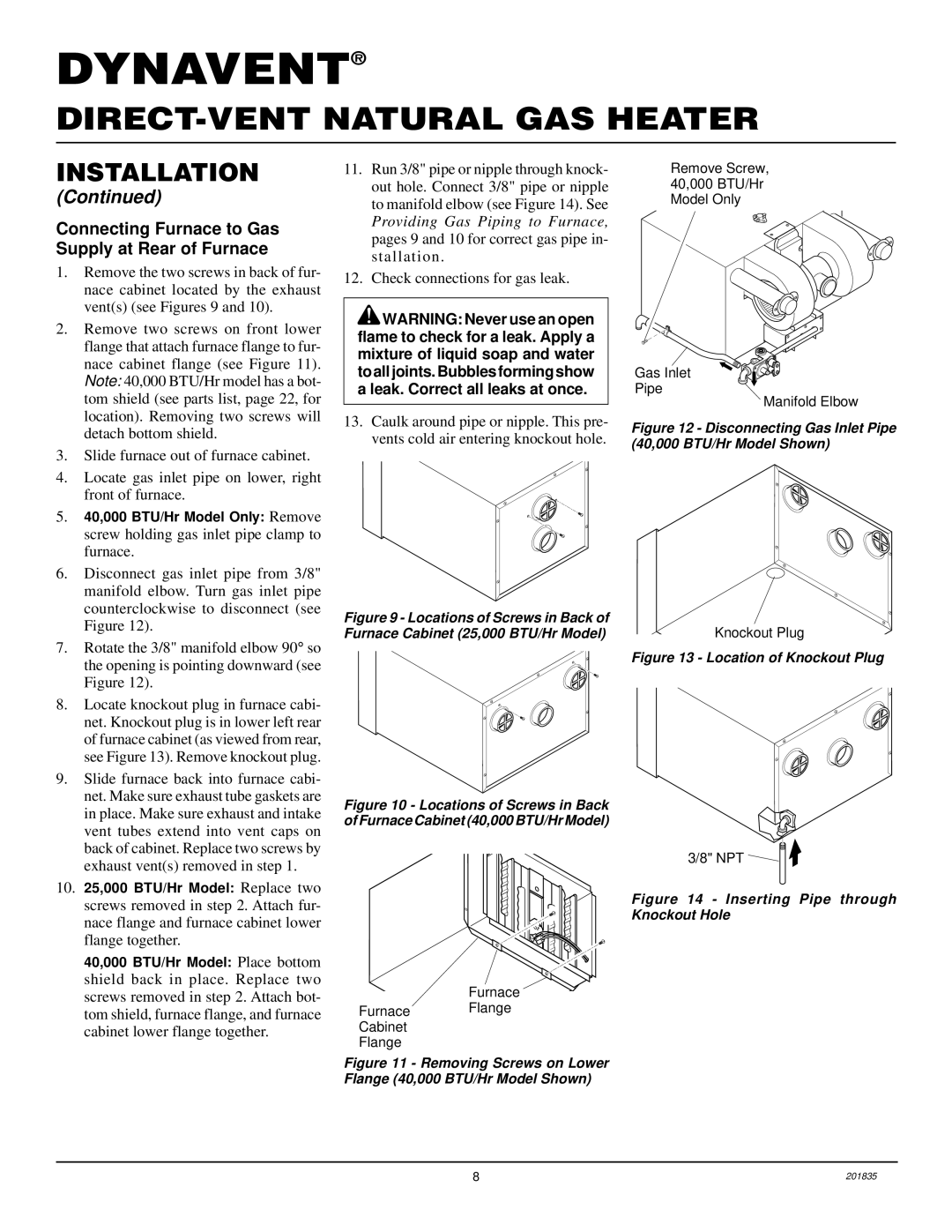
1.Remove the two screws in back of fur- nace cabinet located by the exhaust vent(s) (see Figures 9 and 10).

2.Remove two screws on front lower flange that attach furnace flange to fur- nace cabinet flange (see Figure 11). Note: 40,000 BTU/Hr model has a bot- tom shield (see parts list, page 22, for location). Removing two screws will detach bottom shield.

3.Slide furnace out of furnace cabinet.

4.Locate gas inlet pipe on lower, right front of furnace.

5.40,000 BTU/Hr Model Only: Remove screw holding gas inlet pipe clamp to furnace.

6.Disconnect gas inlet pipe from 3/8" manifold elbow. Turn gas inlet pipe counterclockwise to disconnect (see Figure 12).

7.Rotate the 3/8" manifold elbow 90° so the opening is pointing downward (see Figure 12).

8.Locate knockout plug in furnace cabi- net. Knockout plug is in lower left rear of furnace cabinet (as viewed from rear, see Figure 13). Remove knockout plug.

9.Slide furnace back into furnace cabi- net. Make sure exhaust tube gaskets are in place. Make sure exhaust and intake vent tubes extend into vent caps on back of cabinet. Replace two screws by exhaust vent(s) removed in step 1.

10.25,000 BTU/Hr Model: Replace two screws removed in step 2. Attach fur- nace flange and furnace cabinet lower flange together.

40,000 BTU/Hr Model: Place bottom shield back in place. Replace two screws removed in step 2. Attach bot- tom shield, furnace flange, and furnace cabinet lower flange together.

11.Run 3/8" pipe or nipple through knock- out hole. Connect 3/8" pipe or nipple to manifold elbow (see Figure 14). See Providing Gas Piping to Furnace, pages 9 and 10 for correct gas pipe in- stallation.

12.Check connections for gas leak.

WARNING: Never use an open flame to check for a leak. Apply a mixture of liquid soap and water to all joints. Bubbles forming show a leak. Correct all leaks at once.

13.Caulk around pipe or nipple. This pre- vents cold air entering knockout hole.

Figure 9 - Locations of Screws in Back of Furnace Cabinet (25,000 BTU/Hr Model)

Figure 10 - Locations of Screws in Back of Furnace Cabinet (40,000 BTU/Hr Model)

Furnace

Furnace Flange

Cabinet

Flange

Figure 11 - Removing Screws on Lower Flange (40,000 BTU/Hr Model Shown)

Remove Screw,

40,000 BTU/Hr

Model Only

Gas Inlet

Pipe

Manifold Elbow

Figure 12 - Disconnecting Gas Inlet Pipe (40,000 BTU/Hr Model Shown)

Knockout Plug

Figure 13 - Location of Knockout Plug

3/8" NPT

Figure 14 - Inserting Pipe through Knockout Hole

8

201835

Page 8
Image 8
Desa DNV40NB, DNV25NB installation manual Connecting Furnace to Gas Supply at Rear of Furnace

DNV25NB, DNV40NB specifications

Desa DNV25NB and DNV40NB are contemporary heating solutions designed to meet the demands of modern residential and commercial spaces. Both models integrate advanced technologies, ensuring efficient performance while promoting sustainability and energy conservation.

The DNV25NB is a compact and versatile unit, making it ideal for small to medium-sized environments. It boasts a nominal heating capacity of 25 kW, providing a reliable source of warmth during colder months. One of its main features is the innovative heat pump technology that extracts energy from the environment, thereby lowering electricity consumption compared to traditional heating systems. The unit is also equipped with advanced inverter technology, which allows it to adjust its output according to the heat demand. This results in reduced energy usage and lower utility bills, making it an economical choice for homeowners or businesses aiming to minimize operational costs.

On the other hand, the DNV40NB is designed for larger spaces, offering a robust heating capacity of 40 kW. This model features a dual-stage compressor that enhances its heating efficiency. This technology ensures quick heating response, allowing it to maintain a consistent indoor temperature even in extreme weather conditions. Furthermore, the DNV40NB incorporates smart control systems that enable users to manage settings through a mobile app, providing convenience and remote monitoring capabilities.

Both models are characterized by their eco-friendly refrigerants, which contribute to reduced greenhouse gas emissions. The units are also designed with user-friendly interfaces featuring digital displays, making operation intuitive. Additional safety features, including over-temperature protection and anti-freeze modes, ensure safe usage while prolonging the lifespan of the units.

In terms of installation, both DNV25NB and DNV40NB are designed for easy integration into existing systems. Their compact design enables flexibility in placement without compromising aesthetics. With their reliable performance, energy efficiency, and user-centric technologies, the Desa DNV25NB and DNV40NB offer compelling solutions for those seeking sustainable heating alternatives. Overall, they represent a forward-thinking approach to climate control, combining performance with environmental responsibility.