WHAT TO DO IF YOU SMELL GAS
OWNER’S OPERATION AND INSTALLATION MANUAL
Do not try to light any appliance
UNVENTED VENT-FREEGAS FIREPLACE
TABLE OF CONTENTS
SAFETY INFORMATION
WARNINGS
PRODUCT IDENTIFICATION
Continued
SAFETY INFORMATION
OPTIONAL REMOTE CONTROL ACCESSORY
PRODUCT FEATURES
SAFETY DEVICE
OPTIONAL BLOWER ASSEMBLY ACCESSORY
DETERMINING FRESH-AIRFLOW FOR HEATER LOCATION
PROVIDING ADEQUATE VENTILATION
Unusually Tight Construction
Confined and Unconfined Space
Ventilation Air From Inside Building
VENTILATION AIR
Ventilation Air From Outdoors
AIR FOR COMBUSTION AND VENTILATION
INSTALLING HOOD
INSTALLATION
Blower Accessories, and GA3555 Internal
CHECK GAS TYPE
CONVENTIONAL FIREPLACE INSTALLATION
INSTALLATION CLEARANCES
Included with Mantel Accessory
ASSEMBLING AND ATTACHING OPTIONAL BRASS TRIM
INSTALLATION
INSTALLATION
Access
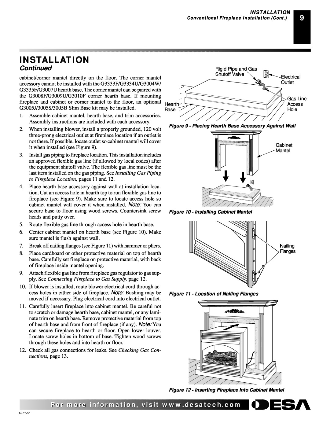
Figure 10 - Installing Cabinet Mantel
Mantel Clearances for Built-InInstallation
BUILT-INFIREPLACE INSTALLATION
INSTALLATION
Continued
Installation Items Needed
INSTALLING GAS PIPING TO FIREPLACE LOCATION
INSTALLATION
Continued
Installation Items Needed
INSTALLATION
Continued
5/16 hex socket wrench or nut-driver
Pressure Testing Fireplace Gas Connections
Pressure Testing gas Supply Piping system
CHECKING GAS CONNECTIONS
INSTALLATION
INSTALLING LOGS
INSTALLATION
Continued
OPERATING FIREPLACE
FOR YOUR SAFETY READ BEFORE LIGHTING
LIGHTING INSTRUCTIONS
INSTALLATION
TO TURN OFF GAS TO APPLIANCE
MANUAL LIGHTING PROCEDURE
OPTIONAL REMOTE OPERATION
Shutting Off Heater
GHRCTA Series Operation
OPTIONAL BLOWER OPERATION
OPERATING FIREPLACE
Continued
PILOT FLAME PATTERN
INSPECTING BURNERS
FRONT BURNER FLAME PATTERN
MAIN BURNER
LOGS
CLEANING AND MAINTENANCE
OBSERVED PROBLEM
TROUBLESHOOTING
POSSIBLE CAUSE
REMEDY
Refer to Air for Combustion and Venti
Maintenance, page
TROUBLESHOOTING
OBSERVED PROBLEM
ing Gas Connections, page
visit
TROUBLESHOOTING
OBSERVED PROBLEM
SPECIFICATIONS
WIRING DIAGRAM
REPLACEMENT PARTS
SERVICE HINTS
ILLUSTRATED PARTS BREAKDOWN
LOG BASE ASSEMBLY EFS33NR, VSGF33NR4
EFS33PR, VSGF33PR Shown
Log Base Assembly
PARTS LIST
PARTS LIST
PART NUMBER
EFS33NR
ILLUSTRATED PARTS BREAKDOWN
FIREPLACE17 EFS33NR,VSGF33NR EFS33PR, VSGF33PR
ILLUSTRATED PARTS BREAKDOWN
Fireplace
PARTS LIST
FIREPLACE EFS33NR, VSGF33NR EFS33PR, VSGF33PR
PARTS LIST
PART NUMBER
BLOWER ACCESSORY GA3700 & GA3700T SERIES
ACCESSORIES
EQUIPMENT SHUTOFF VALVE - GA5010
DUPLEX OUTLET KIT - GA3555 Not Shown
CLEANING KIT - GCK Not Shown
BRASS TRIM ACCESSORY - GA7090 Not Shown
CORNER HEARTH BASE
HARDWOOD HEARTH BASE
WALL-MOUNTON/OFF SWITCH - GWMS2
WALL-MOUNTTHERMOSTAT SWITCH - GWMT1
GHRCTA SERIES
Not Shown
OWNERS REGISTRATION FORM
2701 Industrial Drive P.O. Box Bowling Green, KY
Postage Required
Page
LIMITED WARRANTY VENT-FREEGAS FIREPLACE
KEEP THIS WARRANTY
NOT A UPC
Model Serial No Date Purchased