Desa (F)SVYD18NR Checking GAS Connections, Pressure Testing Heater Gas Connections

Models: (F)SVYD18N (F)SVYD18NR

1 34
Download 34 pages 51.9 Kb
Page 13
Image 13

OWNER’S MANUAL

INSTALLATION

Continued

We recommend that you install a sediment trap in supply line as shown in Figures 20 and 21 on page 12. Locate sediment trap where it is within reach for cleaning. Install in piping system between fuel supply and heater. Locate sediment trap where trapped matter is not likely to freeze. A sediment trap traps moisture and contaminants. This keeps them from going into heater controls. If sediment trap is not installed or is in- stalled wrong, heater may not run properly.

CAUTION: Avoid damage to regulator. Hold gas regulator with wrench when connecting it to gas piping and/or fittings.

CHECKING GAS

CONNECTIONS

WARNING: Test all gas pip- ing and connections for leaks after installing or servicing. Cor- rect all leaks at once.

WARNING: Never use an open flame to check for a leak. Apply a noncorrosive leak detection fluid to all joints. Bubbles forming show a leak. Correct all leaks at once.

4.Check all joints of gas supply piping system. Apply a noncorrosive leak de- tection fluid to gas joints. Bubbles forming show a leak.

5.Correct all leaks at once.

6.Reconnect heater and equipment shutoff valve to gas supply. Check re- connected fittings for leaks.

Test Pressures Equal To or Less Than 1/2 PSIG (3.5 kPa)

1.Close equipment shutoff valve (see Fig- ure 22).

2.Pressurize supply piping system by ei- ther using compressed air or opening main gas valve located on or near gas meter.

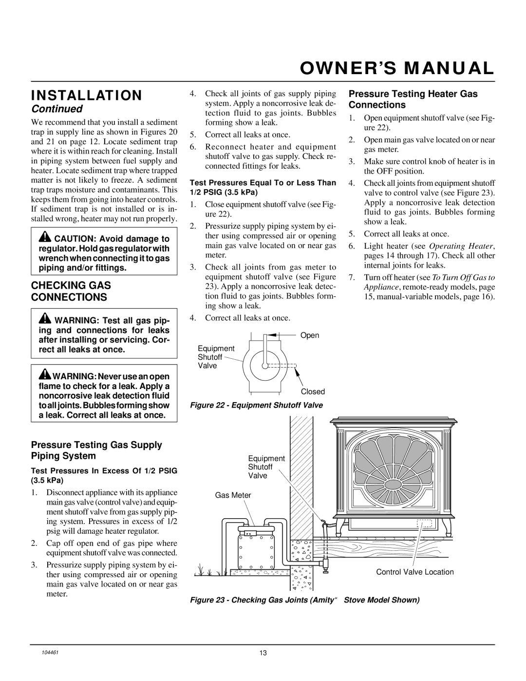
3.Check all joints from gas meter to equipment shutoff valve (see Figure 23). Apply a noncorrosive leak detec- tion fluid to gas joints. Bubbles form- ing show a leak.

4.Correct all leaks at once.

Open

Equipment

Shutoff

Valve

Closed

Figure 22 - Equipment Shutoff Valve

Pressure Testing Heater Gas Connections

1.Open equipment shutoff valve (see Fig- ure 22).

2.Open main gas valve located on or near gas meter.

3.Make sure control knob of heater is in the OFF position.

4.Check all joints from equipment shutoff valve to control valve (see Figure 23). Apply a noncorrosive leak detection fluid to gas joints. Bubbles forming show a leak.

5.Correct all leaks at once.

6.Light heater (see Operating Heater, pages 14 through 17). Check all other internal joints for leaks.

7.Turn off heater (see To Turn Off Gas to Appliance, remote-ready models, page 15, manual-variable models, page 16).

Pressure Testing Gas Supply Piping System

Test Pressures In Excess Of 1/2 PSIG (3.5 kPa)

1.Disconnect appliance with its appliance main gas valve (control valve) and equip- ment shutoff valve from gas supply pip- ing system. Pressures in excess of 1/2 psig will damage heater regulator.

2.Cap off open end of gas pipe where equipment shutoff valve was connected.

3.Pressurize supply piping system by ei- ther using compressed air or opening main gas valve located on or near gas meter.

Equipment

Shutoff

Valve

Gas Meter

Control Valve Location

Figure 23 - Checking Gas Joints (Amity™ Stove Model Shown)

104461

13

Page 13
Image 13
Desa (F)SVYD18NR installation manual Checking GAS Connections, Pressure Testing Heater Gas Connections

(F)SVYD18N, (F)SVYD18NR specifications

Desa (F)SVYD18NR and (F)SVYD18N are advanced models in the range of valves designed to serve various industrial and residential applications. Known for their reliability and efficiency, these valves are engineered to meet the demanding needs of modern fluid control systems.

One of the main features of the Desa (F)SVYD18NR and (F)SVYD18N is their robust construction. They are made from high-quality materials that ensure durability and longevity, even in harsh operating conditions. The valves are resistant to corrosion, making them suitable for handling aggressive fluids without compromising their integrity. This characteristic is essential for industries such as chemicals, oil and gas, and water treatment, where exposure to different substances is inevitable.

The valves are also equipped with advanced sealing technologies which prevent leaks and ensure optimal performance. The precision-engineered seals provide a barrier against contaminants while maintaining efficient fluid flow. This not only enhances the reliability of the system but also contributes to reduced maintenance costs and downtime.

Another significant advantage of the Desa (F)SVYD18NR and (F)SVYD18N is their versatility. They are designed to accommodate a wide range of fluid types, including gases, liquids, and slurries. This adaptability makes them ideal for various applications, from HVAC systems to industrial manufacturing processes.

In terms of operation, these valves utilize a user-friendly design that facilitates ease of installation and adjustment. They come with standardized connections that fit a variety of piping systems, simplifying the integration process. Additionally, the models have a responsive actuator mechanism that ensures precise control over fluid flow, enhancing operational efficiency.

Moreover, Desa (F)SVYD18NR and (F)SVYD18N are designed with energy efficiency in mind. Their advanced aerodynamic design minimizes pressure drops and energy consumption, making them an environmentally friendly choice. This aligns with the growing trend of sustainable practices in industrial operations.

Finally, both models are subject to rigorous testing to ensure they meet industry standards and regulations. This commitment to quality assurance guarantees that users can trust the performance and safety of these valves in their operations.

In conclusion, the Desa (F)SVYD18NR and (F)SVYD18N valves stand out for their durability, versatility, easy installation, and commitment to energy efficiency. These characteristics make them an excellent choice for anyone seeking reliable fluid control solutions in various applications.