OWNER’S MANUAL

INSTALLATION

Continued

Test Pressures Equal To or Less Than 1/2 PSIG

1.Close manual shutoff valve (see Fig- ure 7).

2.Pressurize supply piping system by either using compressed air or opening main gas valve located on or near gas meter.

3.Check all joints from gas meter to manual shutoff valve (see Figure 7). Apply mix- ture of liquid soap and water to gas joints. Bubbles forming show a leak.

4.Correct all leaks at once.

Manual Shutoff Valve

Gas Meter

Figure 7 - Checking Gas Joints

HEARTH KIT ASSEMBLY AND INSTALLATION

Kit Assembly

Note: Be sure all pipe threaded connections are tight, and have thread compound to pre- vent leaks.

1.Determine which side the gas line will be coming into the fireplace.

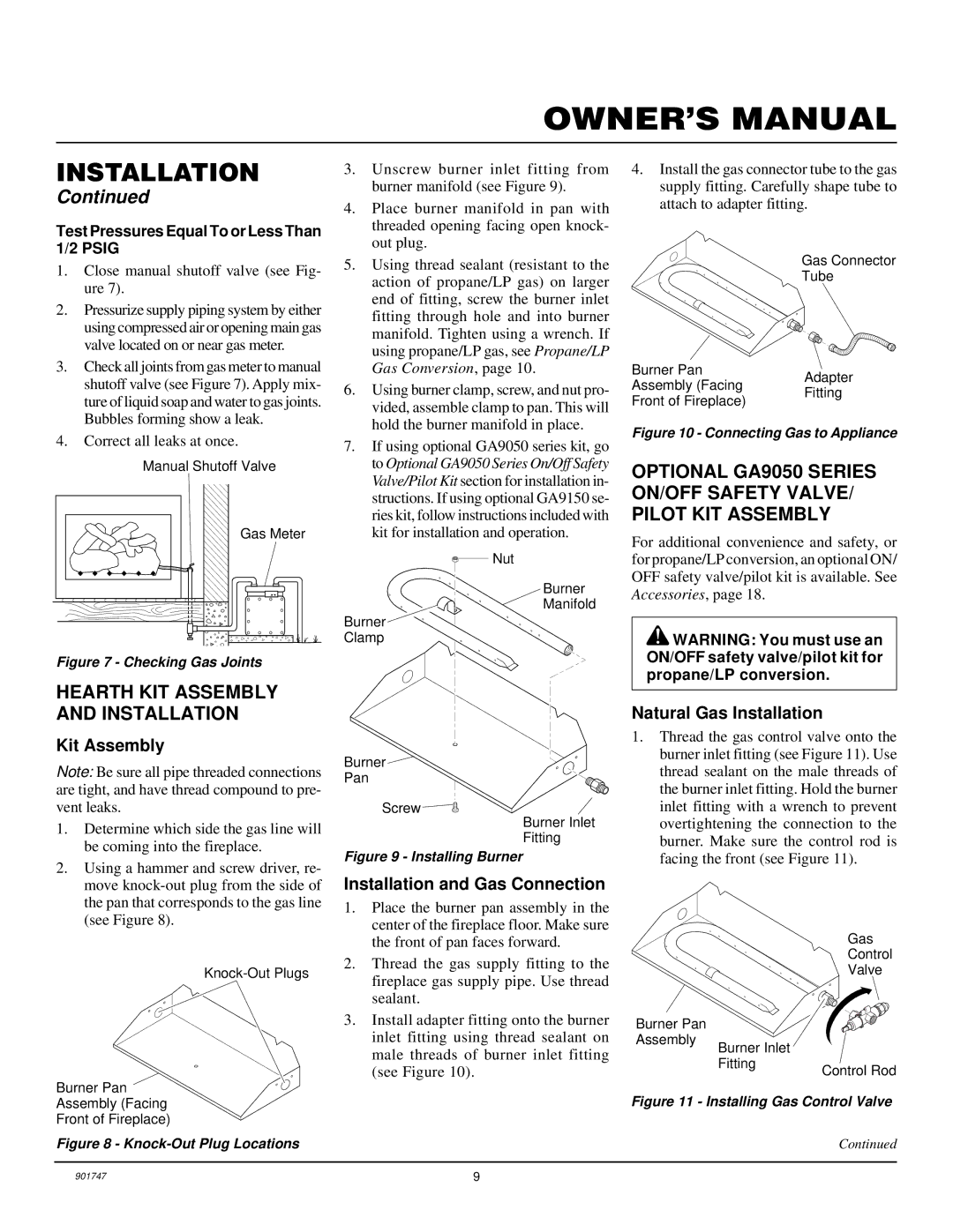
2.Using a hammer and screw driver, re- move knock-out plug from the side of the pan that corresponds to the gas line (see Figure 8).

Knock-Out Plugs

Burner Pan

Assembly (Facing

Front of Fireplace)

Figure 8 - Knock-Out Plug Locations

3.Unscrew burner inlet fitting from burner manifold (see Figure 9).

4.Place burner manifold in pan with threaded opening facing open knock- out plug.

5.Using thread sealant (resistant to the action of propane/LP gas) on larger end of fitting, screw the burner inlet fitting through hole and into burner manifold. Tighten using a wrench. If using propane/LP gas, see Propane/LP Gas Conversion, page 10.

6.Using burner clamp, screw, and nut pro- vided, assemble clamp to pan. This will hold the burner manifold in place.

7.If using optional GA9050 series kit, go to Optional GA9050 Series On/Off Safety Valve/Pilot Kit section for installation in- structions. If using optional GA9150 se- ries kit, follow instructions included with kit for installation and operation.

Nut

Burner

Manifold

Burner

Clamp

Burner

Pan

Screw

Burner Inlet

Fitting

Figure 9 - Installing Burner

Installation and Gas Connection

1.Place the burner pan assembly in the center of the fireplace floor. Make sure the front of pan faces forward.

2.Thread the gas supply fitting to the fireplace gas supply pipe. Use thread sealant.

3.Install adapter fitting onto the burner inlet fitting using thread sealant on male threads of burner inlet fitting (see Figure 10).

4.Install the gas connector tube to the gas supply fitting. Carefully shape tube to attach to adapter fitting.

Gas Connector

Tube

Burner Pan

Adapter

Assembly (Facing

Fitting

Front of Fireplace)


Figure 10 - Connecting Gas to Appliance

OPTIONAL GA9050 SERIES ON/OFF SAFETY VALVE/ PILOT KIT ASSEMBLY

For additional convenience and safety, or for propane/LP conversion, an optional ON/ OFF safety valve/pilot kit is available. See Accessories, page 18.

WARNING: You must use an ON/OFF safety valve/pilot kit for propane/LP conversion.

Natural Gas Installation

1.Thread the gas control valve onto the burner inlet fitting (see Figure 11). Use thread sealant on the male threads of the burner inlet fitting. Hold the burner inlet fitting with a wrench to prevent overtightening the connection to the burner. Make sure the control rod is facing the front (see Figure 11).

Gas

Control

Valve

Burner Pan


Assembly

Burner Inlet


Fitting

Control Rod


Figure 11 - Installing Gas Control Valve

Continued

901747

9

Page 9
Image 9
Desa PCVDR24 RGA installation manual Hearth KIT Assembly and Installation, Kit Assembly, Installation and Gas Connection

PCVDR24 RGA specifications

Desa PCVDR24 RGA is a cutting-edge device designed to enhance temperature management in residential and commercial spaces. This innovative product stands out in the market thanks to its advanced technology and user-friendly features.

At its core, the PCVDR24 RGA offers precise temperature control, allowing users to maintain their desired comfort levels efficiently. It uses a highly responsive digital thermostat, which ensures accurate readings and minimal temperature fluctuations. This feature not only contributes to user comfort but also promotes energy efficiency, as the system avoids unnecessary heating or cooling cycles.

One of the key features of the Desa PCVDR24 RGA is its robust construction. Designed for durability, this unit is built to withstand varying environmental conditions, making it suitable for both indoor and outdoor applications. The materials used in its construction resist rust and corrosion, ensuring a long lifespan even in harsh climates.

The PCVDR24 RGA also employs advanced airflow technology, which facilitates even distribution of heated or cooled air. This ensures that every corner of the room reaches the desired temperature without hot or cold spots, significantly enhancing comfort levels for occupants.

Furthermore, the device is equipped with programmable settings, allowing users to tailor temperature schedules based on their daily routines. This smart feature not only enhances user convenience but also contributes to energy savings, as homeowners and business operators can adjust the heating and cooling cycles to operate according to their specific needs.

Additionally, the Desa PCVDR24 RGA comes with a built-in safety mechanism designed to prevent overheating. This greatly reduces the risk of potential accidents, ensuring a safe environment for all users.

In terms of energy efficiency, the PCVDR24 RGA is designed to meet rigorous industry standards, making it an environmentally friendly choice. Users can expect a reduction in energy bills due to its efficient operation, which is increasingly important in today’s eco-conscious society.

In summary, the Desa PCVDR24 RGA combines advanced technology, robust construction, and user-friendly features to provide a reliable solution for temperature management. Its precise control, even airflow distribution, programmable settings, and safety features make it an attractive option for anyone looking to improve comfort and energy efficiency in their space.