PRODUCT | Hot Air Outlet | Handle |
IDENTIFICATION |
| Upper Shell |
|
| |
| Lower Shell | Fan Guard |
| Fuel Tank | Air Filter |
| End Cover | |
| Side Cover | Fuel Cap |
|
| |
|
| |
| Reset Button |
|
| Power Cord |
|
|
| Figure 1 |
UNPACKING | 1. Remove all packing items applied to heater for shipment. | |
| ||
2.Remove all items from carton.
3.Check items for shipping damage. If heater is damaged, promptly inform dealer where you bought heater.
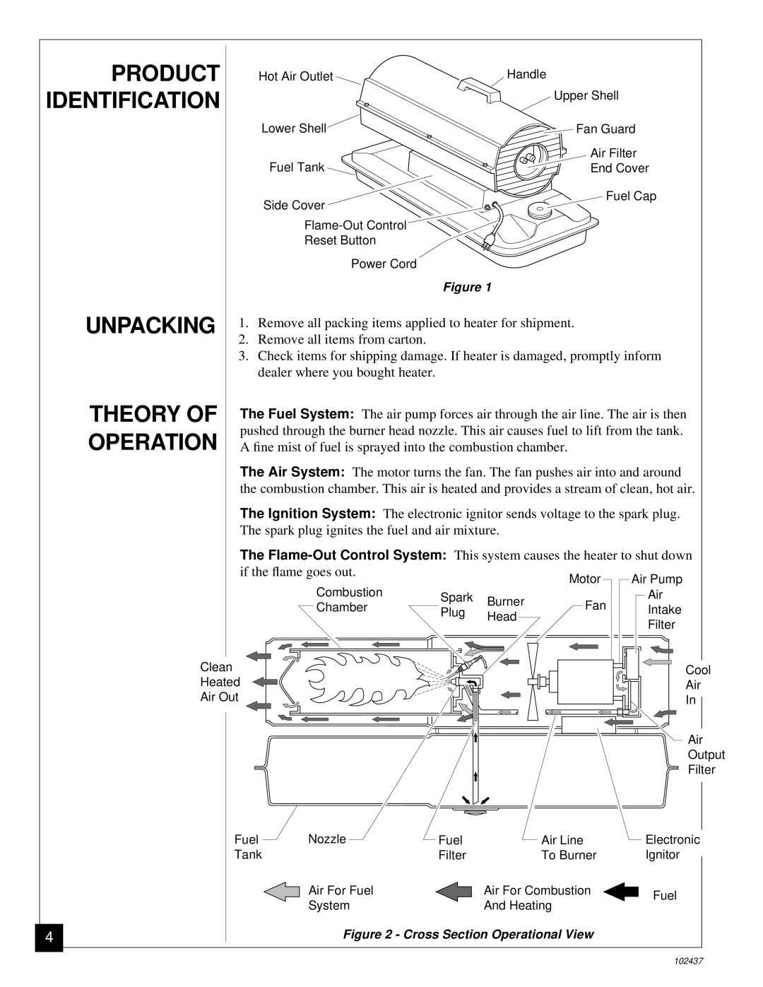
THEORY OF | The Fuel System: The air pump forces air through the air line. The air is then |
OPERATION | pushed through the burner head nozzle. This air causes fuel to lift from the tank. |
A fine mist of fuel is sprayed into the combustion chamber. | |
| The Air System: The motor turns the fan. The fan pushes air into and around |
| the combustion chamber. This air is heated and provides a stream of clean, hot air. |
| The Ignition System: The electronic ignitor sends voltage to the spark plug. |
| The spark plug ignites the fuel and air mixture. |
The | |||||
if the flame goes out. |
|
| Motor | Air Pump | |
Combustion |
|
| |||
Spark | Burner | Fan | Air | ||
Chamber | Plug | Intake | |||
Head | |||||
|
|
| Filter | ||
|
|
|
| ||
Clean |
|
|
| Cool | |
Heated |
|
|
| Air | |
Air Out |
|
|
| In | |
|
|
|
| Air | |
|
|
|
| Output | |
|
|
|
| Filter | |
| Fuel | Nozzle | Fuel | Air Line | Electronic |
|
|
| Tank |
| Filter | To Burner | Ignitor |
|
|
|
|
|
| ||||
|
| Air For Fuel |
| Air For Combustion | Fuel |
| |
|
| System |
| And Heating |
| ||
|
|
|
|
|
| ||
|
| Figure 2 - Cross Section Operational View |
|
|
| ||
4 |
|
|
|
| |||
|
|
|
|
|
|
|
|
|
|
|
|
|
|
|
|
102437