WIRING DIAGRAMS SPECIFICATIONS
21
WIRING DIAGRAMS
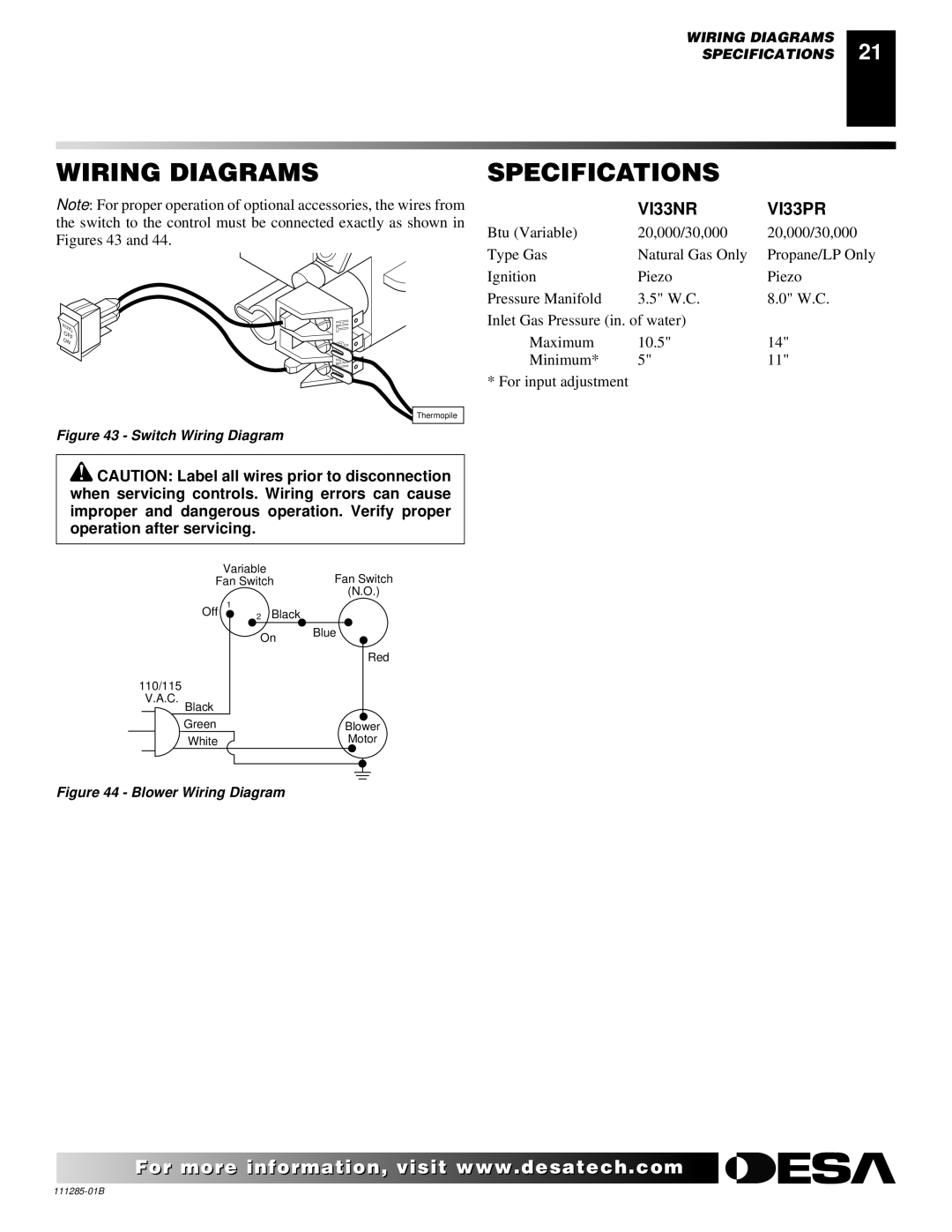
Note: For proper operation of optional accessories, the wires from the switch to the control must be connected exactly as shown in Figures 43 and 44.
A |
|
UT | |
O | |
OF | |
O | F |
N |
|
Thermopile
Figure 43 - Switch Wiring Diagram
![]() CAUTION: Label all wires prior to disconnection when servicing controls. Wiring errors can cause improper and dangerous operation. Verify proper operation after servicing.
CAUTION: Label all wires prior to disconnection when servicing controls. Wiring errors can cause improper and dangerous operation. Verify proper operation after servicing.
Variable
Fan SwitchFan Switch
(N.O.)
Off 1 | 2 Black |
On Blue
Red
110/115
V.A.C.
Black
Green | Blower |
White | Motor |
Figure 44 - Blower Wiring Diagram
SPECIFICATIONS
| VI33NR | VI33PR |
Btu (Variable) | 20,000/30,000 | 20,000/30,000 |
Type Gas | Natural Gas Only | Propane/LP Only |
Ignition | Piezo | Piezo |
Pressure Manifold | 3.5" W.C. | 8.0" W.C. |
Inlet Gas Pressure (in. of water) |
| |
Maximum | 10.5" | 14" |
Minimum* | 5" | 11" |
* For input adjustment |
|
|
For more![]()
![]()
![]()
![]() visit www.
visit www.![]()
![]()
![]() .com
.com![]()
![]()
![]()
![]()
![]()
