8

VENTING INSTALLATION INSTRUCTIONS

Installation Planning

VENTING INSTALLATION INSTRUCTIONS

Continued

INSTALLATION PLANNING

There are two basic types of direct-vent installation:

Horizontal Termination

Vertical Termination

Horizontal Termination Installation

IMPORTANT: Horizontal square terminations require only inner portion of wall firestop. Horizontal installations using round termi- nation require exterior portion of wall firestop available only in vent kit 01491 (see Figure 14, page 10).

1.Set the fireplace in its desired location and determine the route your horizontal venting will take. Do not secure the fireplace until all venting has been installed. Some installations require sliding the fireplace in and out of position to make final vent- ing connections. Figures 14 through 18 on pages 10 through 12 show different configurations for venting with horizontal termination that will help you decide which application best suits your installation. Check to see if wall studs or roof rafters are in the path of your desired venting route. If they are, you may want to adjust the location of the fireplace.

2.Direct vent pipe sections and components are designed with special twist-lock connections.

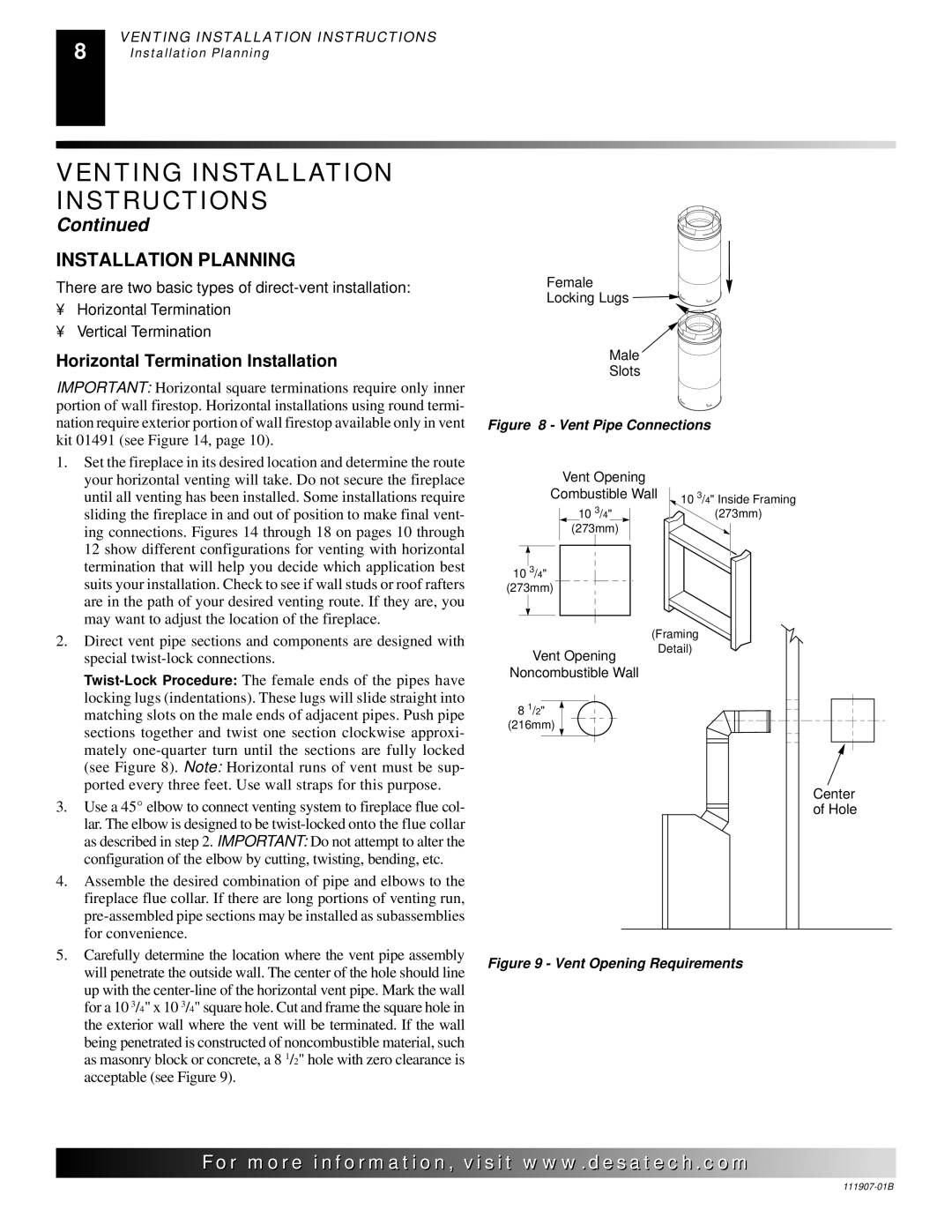
Twist-Lock Procedure: The female ends of the pipes have locking lugs (indentations). These lugs will slide straight into matching slots on the male ends of adjacent pipes. Push pipe sections together and twist one section clockwise approxi- mately one-quarter turn until the sections are fully locked (see Figure 8). Note: Horizontal runs of vent must be sup- ported every three feet. Use wall straps for this purpose.

3.Use a 45° elbow to connect venting system to fireplace flue col- lar. The elbow is designed to be twist-locked onto the flue collar as described in step 2. IMPORTANT: Do not attempt to alter the configuration of the elbow by cutting, twisting, bending, etc.

4.Assemble the desired combination of pipe and elbows to the fireplace flue collar. If there are long portions of venting run, pre-assembled pipe sections may be installed as subassemblies for convenience.

5.Carefully determine the location where the vent pipe assembly will penetrate the outside wall. The center of the hole should line up with the center-line of the horizontal vent pipe. Mark the wall for a 10 3/4" x 10 3/4" square hole. Cut and frame the square hole in the exterior wall where the vent will be terminated. If the wall being penetrated is constructed of noncombustible material, such as masonry block or concrete, a 8 1/2" hole with zero clearance is acceptable (see Figure 9).

Female

Locking Lugs

Male

Slots

Figure 8 - Vent Pipe Connections

Vent Opening


Combustible Wall

10 3/4" Inside Framing

10 3/4"

(273mm)

(273mm)


10 3/4"


(273mm)


(Framing

Vent Opening

Detail)


Noncombustible Wall


8 1/2"


(216mm)


Center


of Hole

Figure 9 - Vent Opening Requirements

For..com

111907-01B

Page 8
Image 8
Desa V)V42EPA(1) SERIES, V)V42ENA(1) SERIES installation manual Installation Planning, Horizontal Termination Installation

V)V42EPA(1) SERIES, V)V42ENA(1) SERIES specifications

The Desa V)V42EPA(1) and V)V42ENA(1) series represent a significant advancement in energy-efficient technologies, emphasizing performance, environmental sustainability, and user comfort. These innovative products have been meticulously designed for various applications, catering to residential, commercial, and industrial energy needs.

One of the standout features of the V)V42EPA(1) and V)V42ENA(1) series is their exceptional energy efficiency. Equipped with advanced integrated circuit technology, these devices optimize power consumption, reducing utility bills while minimizing carbon footprint. The utilization of cutting-edge materials in their construction ensures durability and long-lasting performance, making them an excellent investment for users seeking reliability.

The V)V42EPA(1) series integrates innovative heat exchange technology, allowing for superior thermal performance. This feature ensures quick heat delivery, enhancing overall efficiency while maintaining a comfortable indoor environment. Additionally, the models within this series are designed to operate quietly, making them suitable for settings where noise reduction is paramount, such as homes and offices.

Meanwhile, the V)V42ENA(1) series boasts advanced air filtration capabilities. These units incorporate sophisticated purification systems that significantly reduce allergens, dust, and other pollutants from the air. This feature not only contributes to improved indoor air quality but also facilitates a healthier living or working environment.

Another critical characteristic of both series is their user-friendly interface. They are equipped with intuitive control panels that simplify adjustments and enhance user experience. Remote control capabilities further allow users to manage settings from a distance, adding convenience to day-to-day operation.

The smart technology integration in the V)V42EPA(1) and V)V42ENA(1) series enables connectivity with smart home systems. This functionality allows users to monitor and control their energy consumption seamlessly, further promoting an eco-friendly lifestyle.

Both series are also designed with sustainability in mind. They utilize refrigerants with lower global warming potential, aligning with international environmental standards. This commitment to sustainability not only benefits the planet but also ensures compliance with regulatory requirements.

In conclusion, the Desa V)V42EPA(1) and V)V42ENA(1) series offer a blend of efficiency, comfort, and eco-friendliness. With their advanced technologies, user-centric design, and commitment to sustainability, these series set a benchmark in the energy solutions market, making them ideal choices for anyone looking to improve their energy management and overall indoor environment.