8

VENTING INSTALLATION INSTRUCTIONS Installation Planning

VENTING INSTALLATION INSTRUCTIONS

Continued

INSTALLATION PLANNING

There are two basic types of direct-vent installation:

Horizontal Termination

Vertical Termination

Horizontal Termination Installation

IMPORTANT: Horizontal square terminations require only in- ner portion of wall firestop. Horizontal installations using round termination require exterior portion of wall firestop (see Figure 14, page 10).

1.Set the fireplace in its desired location and determine the route your horizontal venting will take. Do not secure the fireplace until all venting has been installed. Some installations require sliding the fireplace in and out of position to make final vent- ing connections. Figures 14 through 18 on pages 10 through 12 show different configurations for venting with horizontal termination that will help you decide which application best suits your installation. Check to see if wall studs or roof rafters are in the path of your desired venting route. If they are, you may want to adjust the location of the fireplace.

2.Direct vent pipe sections and components are designed with special twist-lock connections.

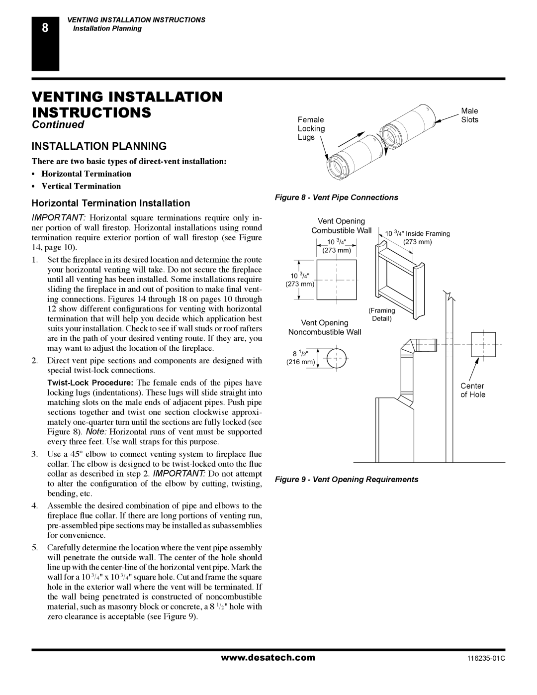
Twist-Lock Procedure: The female ends of the pipes have locking lugs (indentations). These lugs will slide straight into matching slots on the male ends of adjacent pipes. Push pipe sections together and twist one section clockwise approxi- mately one-quarter turn until the sections are fully locked (see Figure 8). Note: Horizontal runs of vent must be supported every three feet. Use wall straps for this purpose.

3.Use a 45° elbow to connect venting system to fireplace flue collar. The elbow is designed to be twist-locked onto the flue collar as described in step 2. IMPORTANT: Do not attempt to alter the configuration of the elbow by cutting, twisting, bending, etc.

4.Assemble the desired combination of pipe and elbows to the fireplace flue collar. If there are long portions of venting run, pre-assembled pipe sections may be installed as subassemblies for convenience.

5.Carefully determine the location where the vent pipe assembly will penetrate the outside wall. The center of the hole should line up with the center-line of the horizontal vent pipe. Mark the wall for a 10 3/4" x 10 3/4" square hole. Cut and frame the square hole in the exterior wall where the vent will be terminated. If the wall being penetrated is constructed of noncombustible material, such as masonry block or concrete, a 8 1/2" hole with zero clearance is acceptable (see Figure 9).

Male

Female Slots

Locking

Lugs

Figure 8 - Vent Pipe Connections

Vent Opening


Combustible Wall

10 3/4" Inside Framing

10 3/4"

(273 mm)

(273 mm)


10 3/4"


(273 mm)


(Framing

Vent Opening

Detail)


Noncombustible Wall


8 1/2"


(216 mm)


Center


of Hole

Figure 9 - Vent Opening Requirements

www.desatech.com

116235-01C

Page 8
Image 8
Desa (V)VC36NE Installation Planning, Horizontal Termination Installation, Male Female Slots Locking Lugs, Center

(V)VC36NE, (V)VC36PE specifications

Desa (V)VC36NE and (V)VC36PE are advanced probe technology designed for precise diagnostic and measurement applications in various industries, including manufacturing, automotive, and healthcare. These models are representative of Desa's commitment to innovation and excellence in engineering, providing users with essential features and cutting-edge technologies.

One of the main features of the (V)VC36NE model is its enhanced resolution, allowing for accurate data collection even in the most challenging environments. This high-resolution capability makes it ideal for detailed inspections and quality control, ensuring that manufacturers can meet stringent performance standards. Meanwhile, the (V)VC36PE model is equipped with a user-friendly interface that simplifies data interpretation, making it accessible to operators with varying levels of technical expertise.

Both models utilize advanced sensing technologies, including capacitive and resistive sensing, enabling them to capture real-time data with exceptional precision. This technology effectively reduces the margin for error, which is critical in applications where even minor discrepancies can lead to significant consequences. Furthermore, the integration of wireless communication in these models allows for seamless data transmission, enhancing connectivity and facilitating remote monitoring capabilities.

Another characteristic that sets Desa's (V)VC36NE and (V)VC36PE apart is their durability. Constructed with high-grade materials, they are designed to withstand harsh operating conditions, ensuring longevity and reliability. This robustness means that users can depend on these probes for consistent performance over time, reducing downtime and maintenance costs.

The versatility of the (V)VC36NE and (V)VC36PE models is another notable advantage. They are compatible with a broad range of accessories and can be easily integrated into existing systems, making them suitable for various applications across different sectors. Whether for industrial automation or healthcare diagnostics, these models provide excellent adaptability.

In conclusion, Desa’s (V)VC36NE and (V)VC36PE probes exemplify the brand's focus on delivering high-performance, reliable, and user-centric diagnostic solutions. Their advanced features, including high resolution, durable construction, and versatile compatibility, make them invaluable tools in modern industries, enhancing productivity and efficiency while ensuring high-quality outcomes.