Manuals
/
Desa
/
Household Appliance
/
Indoor Fireplace
Desa
(V)VC36PE Series Illustrated Parts Breakdown, Models VC36NE, VVC36NE, VC36PE and VVC36PE
Models:
(V)VC36PE Series
1
36
40
40
Download
40 pages
9.94 Kb
33
34
35
36
37
38
39
40
Troubleshooting
Specification
Install
Parts list
Blower Wiring Diagram
Check wiring connection
Warranty
Maintenance
Accessories
Pilot Assembly
Page 36
Image 36
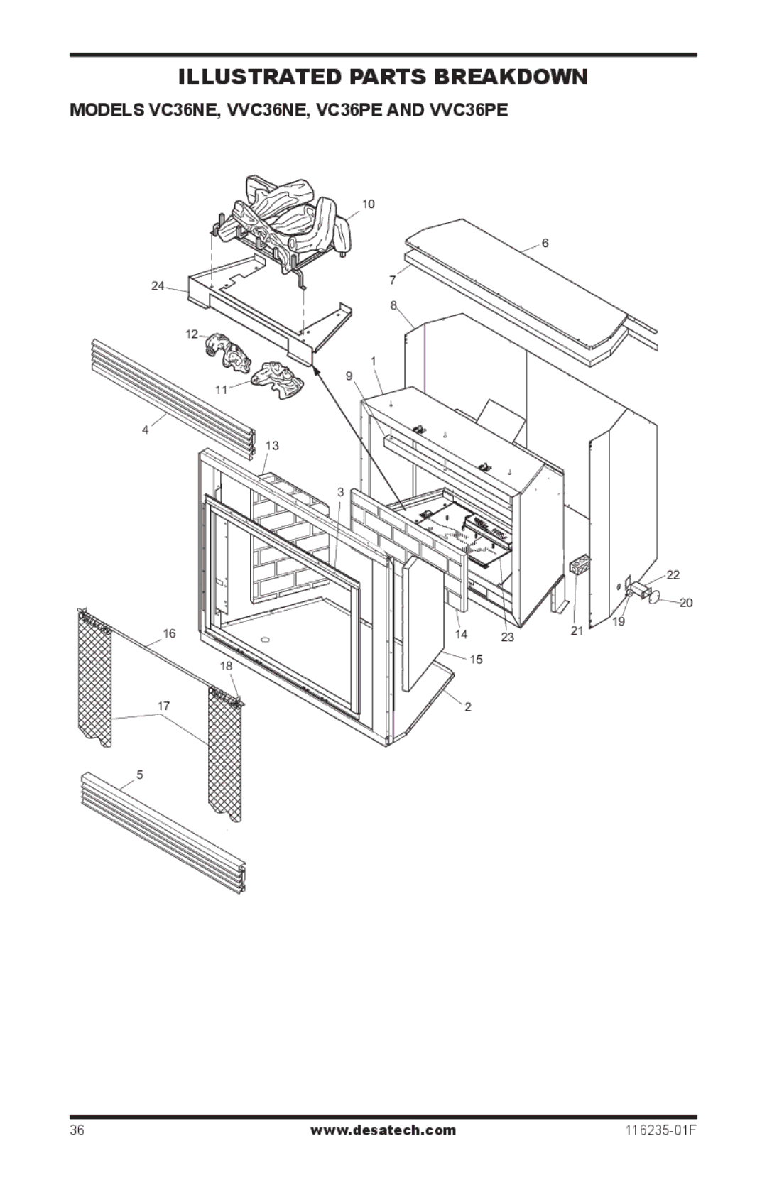
Illustrated Parts Breakdown
Models VC36NE, VVC36NE, VC36PE and VVC36PE
24
12
11
4
13
16
18
17
5
10
7
8
1
9
3
14
23
15
2
6
21
22
20 19
36
www.desatech.com
116235-01F
Page 35
Page 37
Page 36
Image 36
Page 35
Page 37
Contents
What to do if YOU Smell GAS
Table of Contents
Safety Information
Product Identification
High traffic areas
Product Features
Pre-Installation Preparation
Local Codes
Location and space requirements
Clearances
42 1067 mm
Front 36 914 mm Top of Standoffs Vent See venting
Venting clearances
Framing and finishing
Noncombustible mantels at any height above
Fireplace
Location of Termination Cap
Termination CAP AIR Supply Inlet GAS Meter
Venting Installation Instructions
Installation Precautions
Installation Planning
Installing Horizontal Vent Cap Noncombustible Exterior
Square Termination
Round Termination
Corner Installation
Recommended Applications Corner ground floor installation
Horizontal System Installation Using TWO 90 Elbows
Installation for vertical termination
Flat Ceiling Installation
Connect a section of pipe and extend up through the hole
Twist-lock the vent cap onto the last section of vent pipe
High Altitude Installation
Vertical Venting
Parts list for venting kits and components
Desa 5/8 Pipe & Vent Kits Number Description
Fireplace Installation
Installing optional blower accessories
Model BK Installation
Plug in blower power cord
Model BKT Installation
Blower Model BKT
Installing Gas Piping to Fireplace Location
Blower Wiring Diagram
Installation Items Needed
Connecting Fireplace to GAS Supply
Propane/LP Supply TankExternal Regulator Vent Pointing Down
Checking GAS Connections
Test Pressures Equal To or Less Than Psig 3.5 kPa
Close equipment shutoff valve see Figure
Disconnect fireplace and its individual equip
Pressure Testing Fireplace Gas Connections
Removing/Replacing Glass Door
Removing Louver Panels
Removing Glass Door
Installing lava rock and glowing embers
Installing Brick liner Models BL36DASA and BL36DHASA
Cleaning Glass Door
Wall Switch Installation
Optional Remote control Installation model WRC
Close top and bottom louvers
Wiring Diagram
For your safety Read before lighting
Operating Fireplace
Lighting Instructions
To Turn OFF GAS To Appliance
Operating optional blower accessory
Pilot Assembly
Inspecting Burners
Optional Remote Operation
Cleaning Maintenance
Glass Door
Pilot and burners
Logs
Troubleshooting
Observed Problem Possible Cause Remedy
Venting system
Check wiring connection
Ule And/or check ground wire to
No gas to burner, although wall Wall switch wires defective
Pilot will not stay lit
Gas leak. See Warning
Statement at top
Replacement Parts
Service Hints
Technical Service
Specifications
Accessories
Illustrated Parts Breakdown
Models VC36NE, VVC36NE, VC36PE and VVC36PE
Parts List
2827 19 18
Burner Pan Assembly
Warranty Information
Keep this Warranty
Limited Warranty DIRECT-VENT Fireplace
Top
Page
Image
Contents