6

LOCATION OF TERMINATION CAP

LOCATION OF TERMINATION CAP

D

E V

B L


C


Fixed


V


Closed


F


V


Openable


B

B

B

Openable Fixed Closed

H

V

B

I

V J XG

AM

NN


G


V


G

V K X

V


A

V TERMINATION CAP

X AIR SUPPLY INLET

G GAS METER

RESTRICTED AREA (TERMINATION PROHIBITED)

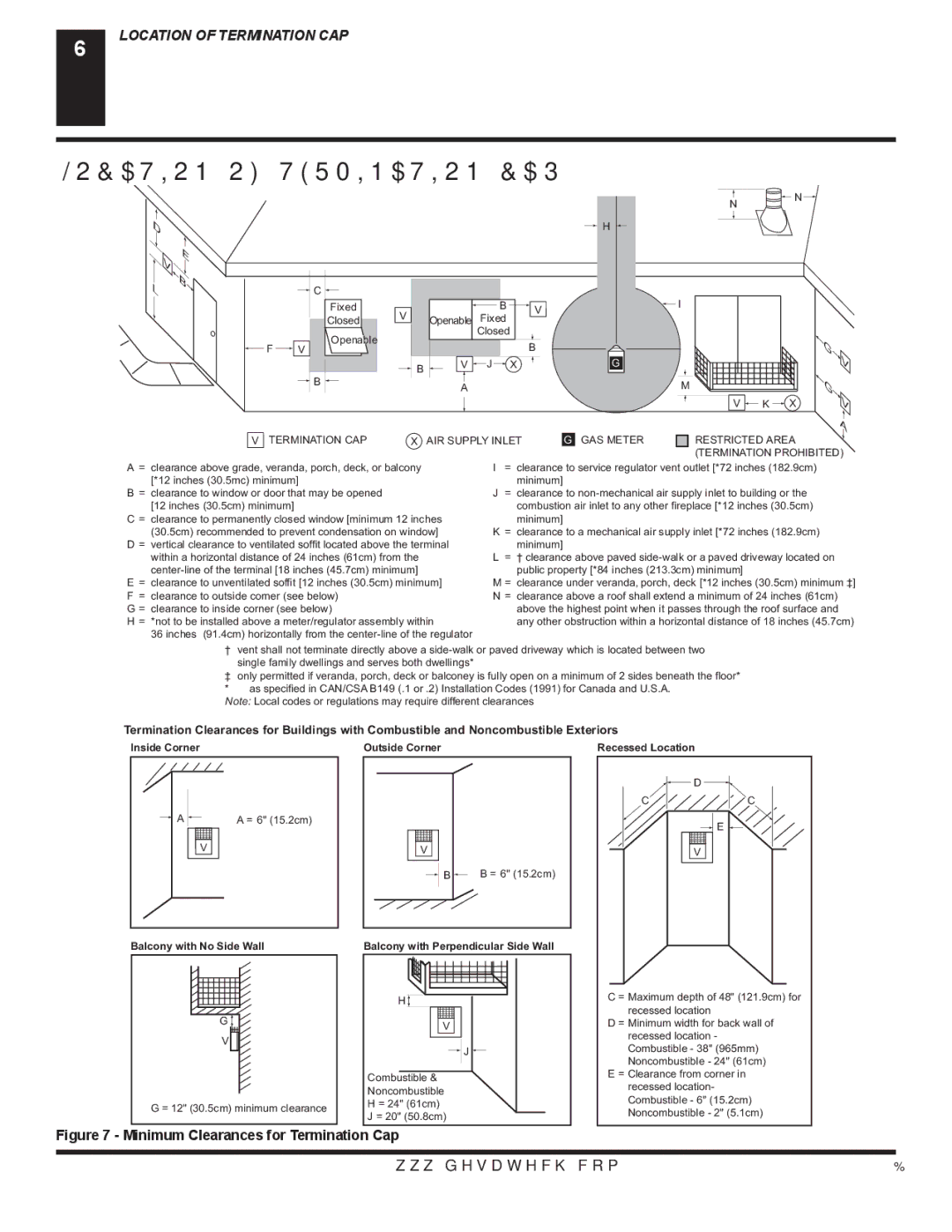
A= clearance above grade, veranda, porch, deck, or balcony [*12 inches (30.5mc) minimum]

B= clearance to window or door that may be opened [12 inches (30.5cm) minimum]

C = clearance to permanently closed window [minimum 12 inches (30.5cm) recommended to prevent condensation on window]

D = vertical clearance to ventilated soffit located above the terminal within a horizontal distance of 24 inches (61cm) from the center-line of the terminal [18 inches (45.7cm) minimum]

E= clearance to unventilated soffit [12 inches (30.5cm) minimum] F = clearance to outside corner (see below)

G = clearance to inside corner (see below)

H = *not to be installed above a meter/regulator assembly within

36 inches (91.4cm) horizontally from the center-line of the regulator

I= clearance to service regulator vent outlet [*72 inches (182.9cm) minimum]

J= clearance to non-mechanical air supply inlet to building or the combustion air inlet to any other fireplace [*12 inches (30.5cm)

minimum]

K= clearance to a mechanical air supply inlet [*72 inches (182.9cm) minimum]

L= † clearance above paved side-walk or a paved driveway located on public property [*84 inches (213.3cm) minimum]

M = clearance under veranda, porch, deck [*12 inches (30.5cm) minimum ‡]

N= clearance above a roof shall extend a minimum of 24 inches (61cm) above the highest point when it passes through the roof surface and any other obstruction within a horizontal distance of 18 inches (45.7cm)

† vent shall not terminate directly above a side-walk or paved driveway which is located between two single family dwellings and serves both dwellings*

only permitted if veranda, porch, deck or balconey is fully open on a minimum of 2 sides beneath the floor* * as specified in CAN/CSA B149 (.1 or .2) Installation Codes (1991) for Canada and U.S.A.

Note: Local codes or regulations may require different clearances

Termination Clearances for Buildings with Combustible and Noncombustible Exteriors

Inside Corner

Outside Corner

Recessed Location

AA = 6" (15.2cm)

V

Balcony with No Side Wall

G

V

G = 12" (30.5cm) minimum clearance

V

B B = 6" (15.2cm)

Balcony with Perpendicular Side Wall

H

V

J

Combustible &

Noncombustible

H = 24" (61cm)

J = 20" (50.8cm)


D

C

C

E

V

C = Maximum depth of 48" (121.9cm) for recessed location

D = Minimum width for back wall of recessed location - Combustible - 38" (965mm) Noncombustible - 24" (61cm)

E = Clearance from corner in recessed location- Combustible - 6" (15.2cm) Noncombustible - 2" (5.1cm)

Figure 7 - Minimum Clearances for Termination Cap

www.desatech.com

116236-01B

Page 6
Image 6
Desa (V)VC42P SERIES, (V)VC42N SERIES Location of Termination CAP, Termination CAP AIR Supply Inlet GAS Meter

(V)VC42P SERIES, (V)VC42N SERIES specifications

The Desa (V)VC42P and (V)VC42N Series are advanced solutions in the HVAC and thermal control industry, designed to provide efficient climate management for various applications. These series are noted for their commitment to performance, reliability, and energy efficiency, making them popular choices among users looking for modern heating and ventilation systems.

One of the main features of the (V)VC42P and (V)VC42N Series is their state-of-the-art variable speed technology. This technology allows the units to adjust their output based on the specific heating or cooling needs of a space. By operating at different speeds, the systems can maintain a more consistent temperature while using less energy compared to traditional fixed-speed systems. This leads to significant cost savings and enhanced comfort for occupants.

Additionally, both series incorporate advanced control systems that can be easily integrated with smart home technologies. Users can remotely monitor and adjust their HVAC systems via mobile applications or voice-activated devices, facilitating greater control over their indoor climate. This compatibility with smart technologies not only enhances user experience but also contributes to energy conservation efforts by allowing for better management of usage patterns.

Another characteristic of the Desa (V)VC42P and (V)VC42N Series is their robust construction and design. Built with high-quality materials, these units demonstrate durability and reliability over time. The compact design of these systems allows for flexible installation options, making them suitable for various residential and commercial environments.

Moreover, the series prioritizes low noise operation, ensuring that the units run quietly without disturbing the peace in homes or workplaces. This feature is particularly essential in settings where noise control is critical, such as in offices, schools, or healthcare facilities.

In summary, the Desa (V)VC42P and (V)VC42N Series stand out in the HVAC market due to their variable speed technology, smart home compatibility, durable construction, and low noise operation. With their innovative features and characteristics, these systems are well-equipped to provide effective and efficient climate control solutions tailored to modern living and working environments.