OPERATING INSTRUCTIONS
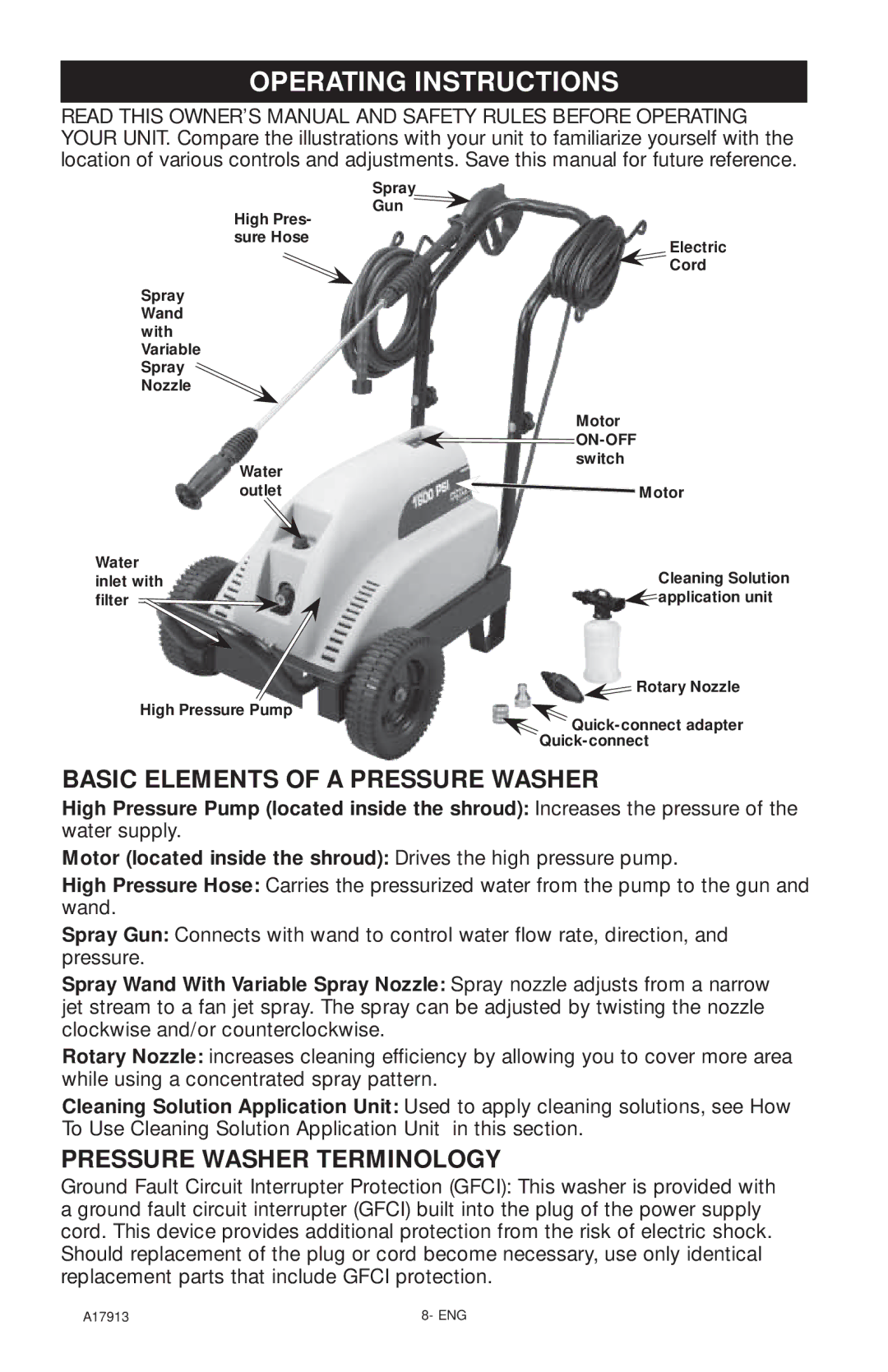
READ THIS OWNER’S MANUAL AND SAFETY RULES BEFORE OPERATING YOUR UNIT. Compare the illustrations with your unit to familiarize yourself with the location of various controls and adjustments. Save this manual for future reference.
Spray
Gun
High Pres- |
|
sure Hose | Electric |
| |
| Cord |
Spray |
|
Wand |
|
with |
|
Variable |
|
Spray |
|
Nozzle |
|
| Motor |
|
|
Water | switch |
| |
outlet | Motor |
Water | Cleaning Solution |
inlet with | |
filter | application unit |
| Rotary Nozzle |
High Pressure Pump | |
| |
|
BASIC ELEMENTS OF A PRESSURE WASHER
High Pressure Pump (located inside the shroud): Increases the pressure of the water supply.
Motor (located inside the shroud): Drives the high pressure pump.
High Pressure Hose: Carries the pressurized water from the pump to the gun and wand.
Spray Gun: Connects with wand to control water flow rate, direction, and pressure.
Spray Wand With Variable Spray Nozzle: Spray nozzle adjusts from a narrow jet stream to a fan jet spray. The spray can be adjusted by twisting the nozzle clockwise and/or counterclockwise.
Rotary Nozzle: increases cleaning efficiency by allowing you to cover more area while using a concentrated spray pattern.
Cleaning Solution Application Unit: Used to apply cleaning solutions, see How To Use Cleaning Solution Application Unit in this section.
PRESSURE WASHER TERMINOLOGY
Ground Fault Circuit Interrupter Protection (GFCI): This washer is provided with a ground fault circuit interrupter (GFCI) built into the plug of the power supply cord. This device provides additional protection from the risk of electric shock. Should replacement of the plug or cord become necessary, use only identical replacement parts that include GFCI protection.
A17913 | 8- ENG |
