ALTERNATE SETUP
The steps so far will assemble the unit with the motor on top and dust intake ports on bottom, as shown in Fig 4.
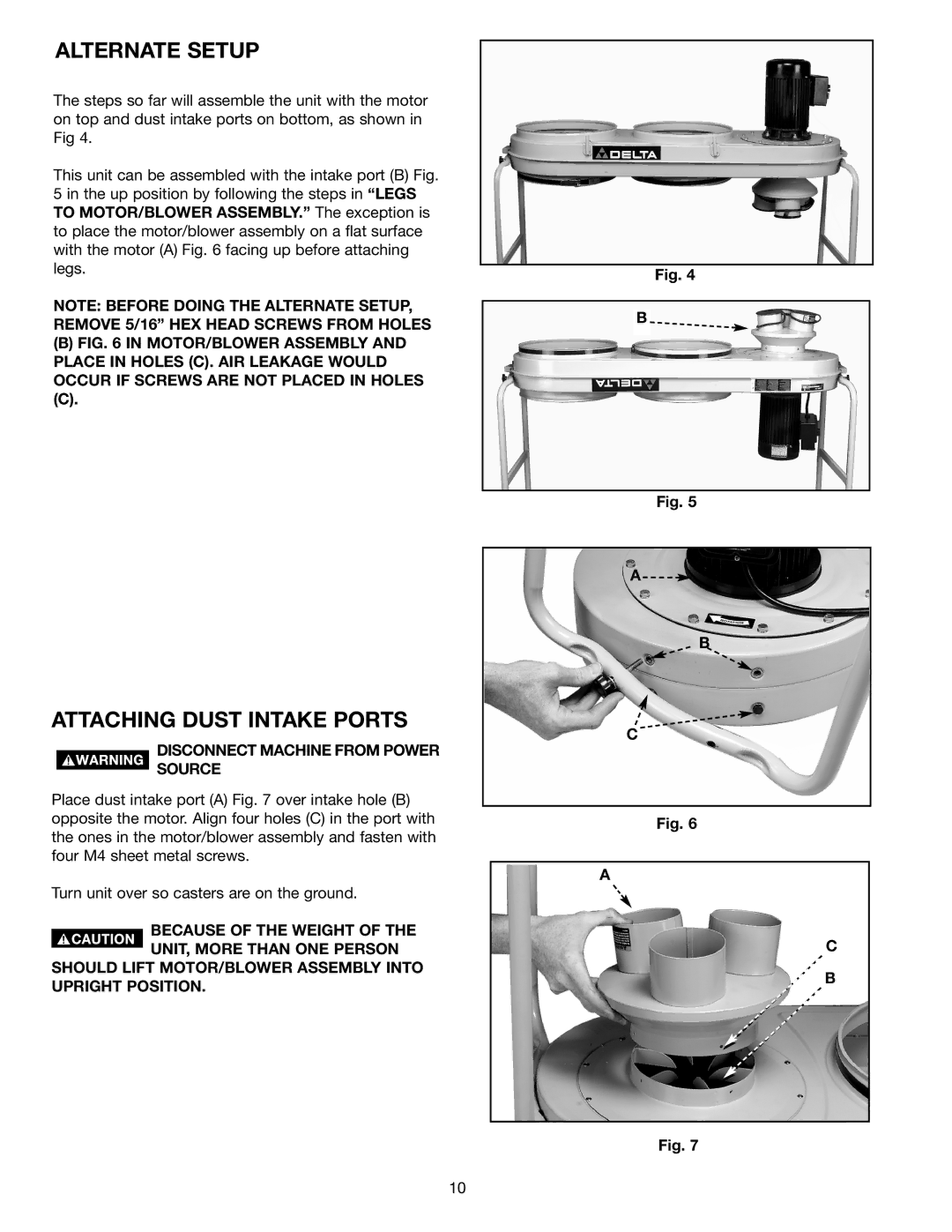
This unit can be assembled with the intake port (B) Fig. 5 in the up position by following the steps in “LEGS TO MOTOR/BLOWER ASSEMBLY.” The exception is to place the motor/blower assembly on a flat surface with the motor (A) Fig. 6 facing up before attaching legs.
NOTE: BEFORE DOING THE ALTERNATE SETUP, REMOVE 5/16” HEX HEAD SCREWS FROM HOLES
(B)FIG. 6 IN MOTOR/BLOWER ASSEMBLY AND PLACE IN HOLES (C). AIR LEAKAGE WOULD OCCUR IF SCREWS ARE NOT PLACED IN HOLES
ATTACHING DUST INTAKE PORTS
DISCONNECT MACHINE FROM POWER
SOURCE
Place dust intake port (A) Fig. 7 over intake hole (B) opposite the motor. Align four holes (C) in the port with the ones in the motor/blower assembly and fasten with four M4 sheet metal screws.
Turn unit over so casters are on the ground.
BECAUSE OF THE WEIGHT OF THE UNIT, MORE THAN ONE PERSON
SHOULD LIFT MOTOR/BLOWER ASSEMBLY INTO UPRIGHT POSITION.
Fig. 4
B
Fig. 5
A![]()
B
C
Fig. 6
A
C
B
Fig. 7
10