SUPPORT
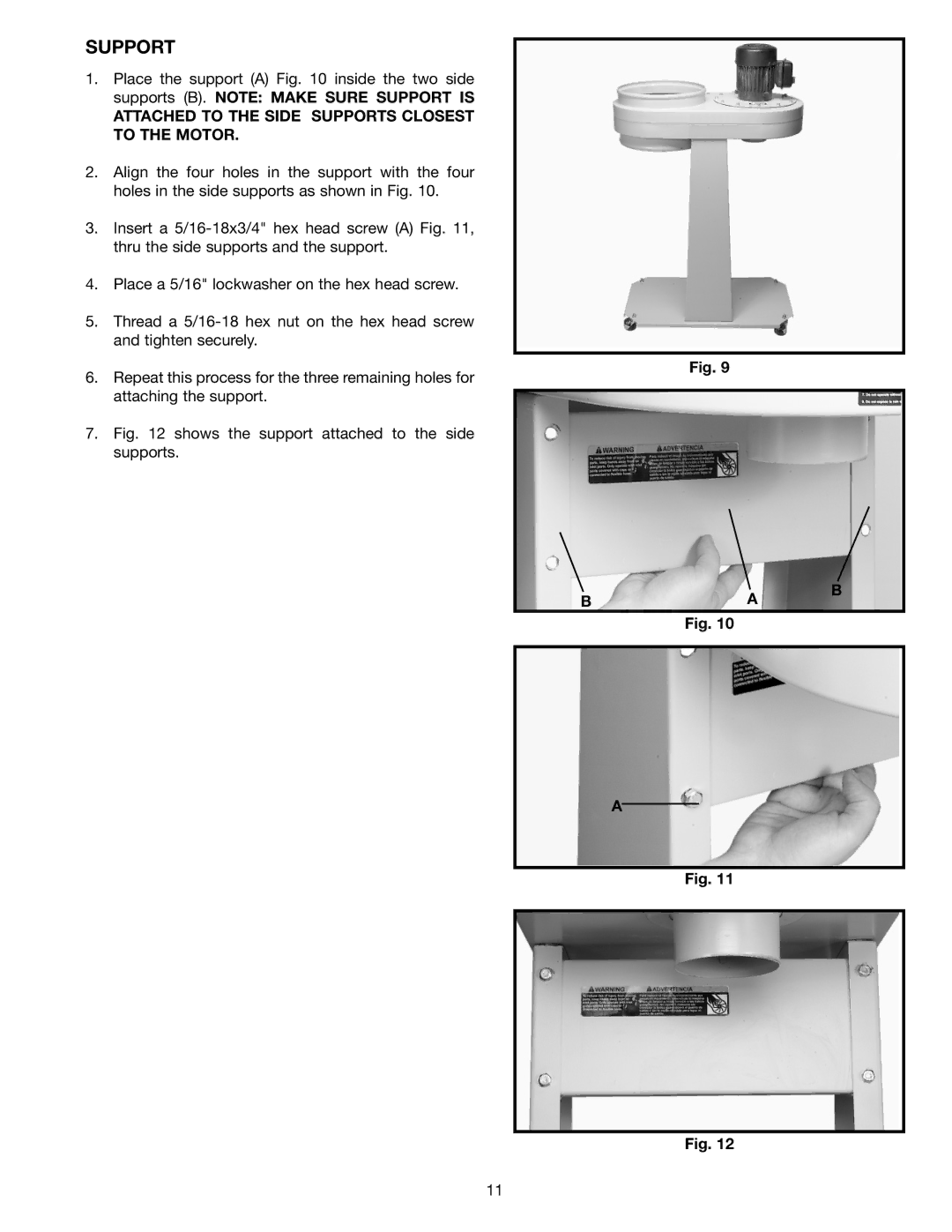
1.Place the support (A) Fig. 10 inside the two side supports (B). NOTE: MAKE SURE SUPPORT IS
ATTACHED TO THE SIDE SUPPORTS CLOSEST TO THE MOTOR.
2.Align the four holes in the support with the four holes in the side supports as shown in Fig. 10.
3.Insert a
4.Place a 5/16" lockwasher on the hex head screw.
5.Thread a
6.Repeat this process for the three remaining holes for attaching the support.
7.Fig. 12 shows the support attached to the side supports.
Fig. 9
B | A | B |
| ||
| Fig. 10 |
|
A
Fig. 11
Fig. 12
11