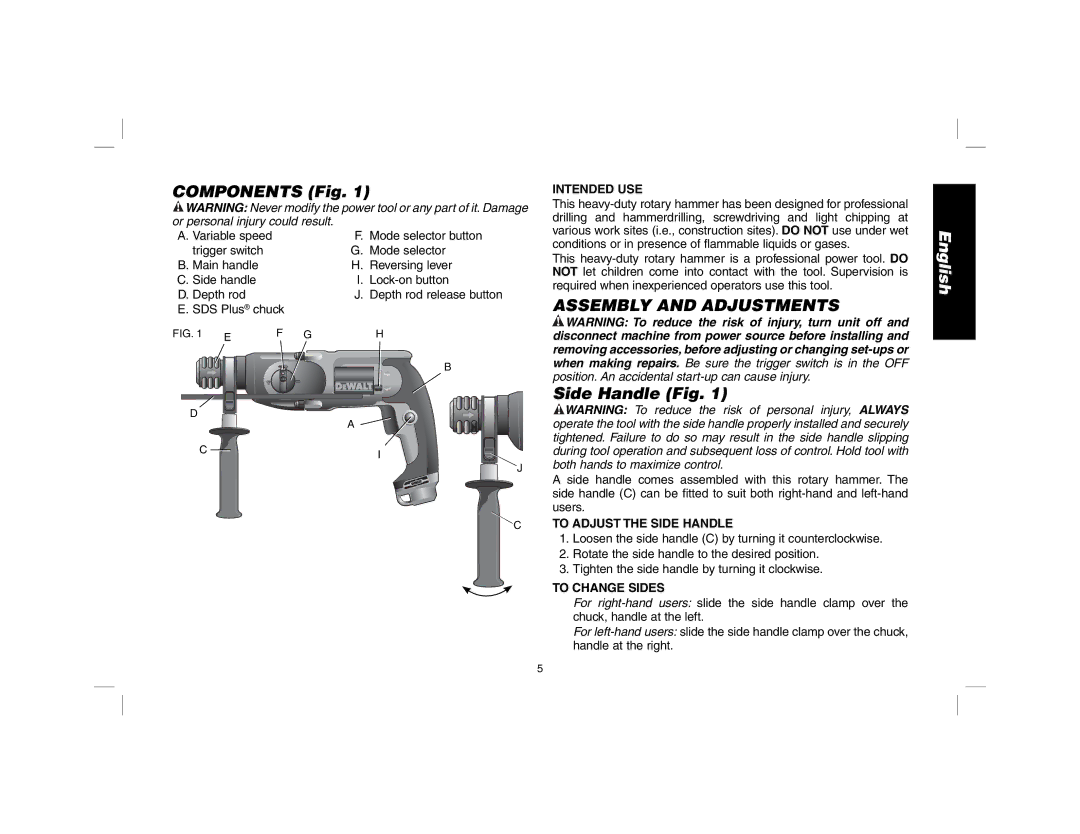
COMPONENTS (Fig. 1)
![]() WARNING: Never modify the power tool or any part of it. Damage
WARNING: Never modify the power tool or any part of it. Damage
or personal injury could result. |
|
A. Variable speed | F. Mode selector button |
trigger switch | G. Mode selector |
B. Main handle | H. Reversing lever |
C. Side handle | I. |
D. Depth rod | J. Depth rod release button |
E. SDS Plus® chuck |
|
INTENDED USE
This
This
ASSEMBLY AND ADJUSTMENTS
English
FIG. 1 | E |
|
D
F GH
B
A
![]() WARNING: To reduce the risk of injury, turn unit off and disconnect machine from power source before installing and removing accessories, before adjusting or changing
WARNING: To reduce the risk of injury, turn unit off and disconnect machine from power source before installing and removing accessories, before adjusting or changing
Side Handle (Fig. 1)
![]() WARNING: To reduce the risk of personal injury, ALWAYS operate the tool with the side handle properly installed and securely
WARNING: To reduce the risk of personal injury, ALWAYS operate the tool with the side handle properly installed and securely
C ![]() I
I
J
C
tightened. Failure to do so may result in the side handle slipping during tool operation and subsequent loss of control. Hold tool with both hands to maximize control.
A side handle comes assembled with this rotary hammer. The side handle (C) can be fitted to suit both
TO ADJUST THE SIDE HANDLE
1.Loosen the side handle (C) by turning it counterclockwise.
2.Rotate the side handle to the desired position.
3.Tighten the side handle by turning it clockwise.
TO CHANGE SIDES
For
For
5
