English
Trigger Switch (Fig. 1)
To start the rotary hammer, depress the trigger switch (A). To stop rotary hammer, release the switch.
NOTE: Use lower speeds for starting holes without a centerpunch, drilling in metal, plastics or ceramics, or driving screws. Higher speeds are better for drilling in masonry for maximum efficiency.
VARIABLE SPEED
The variable speed trigger switch (A) permits speed control. The farther the trigger switch is depressed, the higher the speed of the drill.
LOCK-ON BUTTON
![]() WARNING: Be sure to release the locking mechanism before disconnecting the plug from the power supply. Failure to do so will cause the hammerdrill to start immediately the next time it is plugged in. Damage or personal injury could result.
WARNING: Be sure to release the locking mechanism before disconnecting the plug from the power supply. Failure to do so will cause the hammerdrill to start immediately the next time it is plugged in. Damage or personal injury could result.
The
Before using the tool each time, be sure that the
For continuous operation, press and hold the trigger switch (A); press the
To stop the tool in continuous operation, quickly press and release the trigger switch.
Reversing Lever (Fig. 1)
The reversing lever (H) is used to reverse the rotary hammer for backing out fasteners or jammed bits in
![]() CAUTION: When reversing to clear jammed bits, be ready for strong reactive torque.
CAUTION: When reversing to clear jammed bits, be ready for strong reactive torque.
To reverse the rotary hammer, turn it off and align the reversing lever (H) with the yellow arrow pointing backward (viewed when holding drill in operating position).
To position the lever for forward operation, turn the rotary hammer off and align the reversing lever (H) with the yellow arrow pointing forward (viewed when holding drill in operating position).
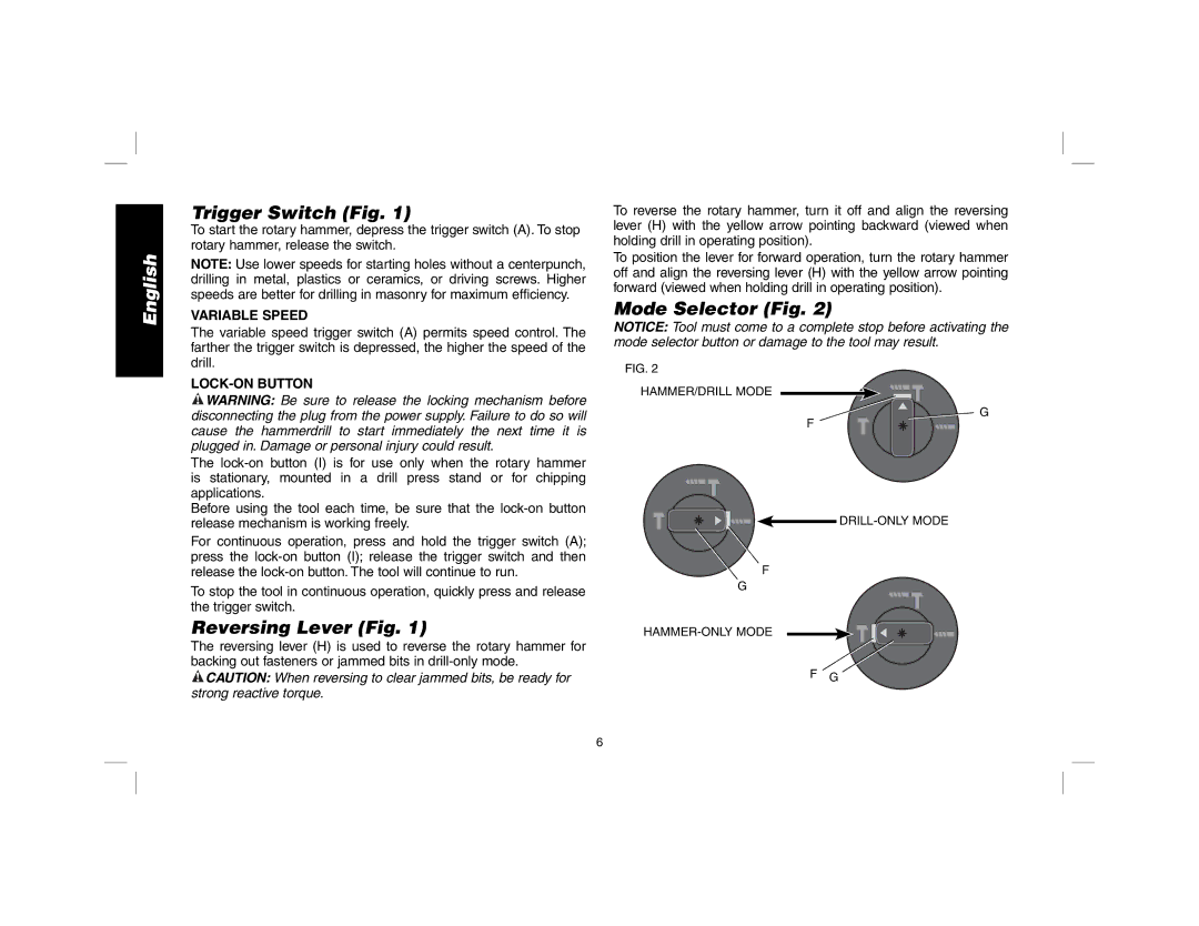
Mode Selector (Fig. 2)
NOTICE: Tool must come to a complete stop before activating the mode selector button or damage to the tool may result.
FIG. 2
HAMMER/DRILL MODE
![]() G
G
F
F
G
F G
6
