English
You may locate the guard to any convenient angle as long as the guard skirt is located between the operator and the acces- sory. Insert and tighten screws to secure guard in place. You should not be able to rotate guard by hand.
3.To rotate the guard, loosen the screws clamping the guard to the tool and rotate as desired. Tighten screws to secure the guard in place.
4.To remove the guard, loosen and remove screws.
NOTE: Edge grinding and cutting can be performed with Type 27 wheels designed and specified for this purpose; 1/4" thick wheels are designed for surface grinding while 1/8" wheels are designed for edge grinding.
MOUNTING AND REMOVING HUBBED WHEELS
![]() CAUTION: Turn off and unplug the tool before making any adjustments or removing or installing attachments or acces- sories. Before reconnecting the tool, actuate and release switch to ensure that the tool is off.
CAUTION: Turn off and unplug the tool before making any adjustments or removing or installing attachments or acces- sories. Before reconnecting the tool, actuate and release switch to ensure that the tool is off.
Hubbed wheels install directly on the 5/8" – 11 threaded spindle.
1.Thread the wheel on the spindle by hand.
2.Depress the spindle lock button and use a wrench to tighten the hub of the wheel.
3.Reverse the above procedure to remove the wheel.
![]() CAUTION: Failure to properly seat the wheel before turning the tool on may result in damage to the tool or the wheel.
CAUTION: Failure to properly seat the wheel before turning the tool on may result in damage to the tool or the wheel.
MOUNTING NON-HUBBED WHEELS
![]() CAUTION: Turn off and unplug the tool before making any adjustments or removing or installing attachments or acces- sories. Before reconnecting the tool, actuate and release switch to ensure that the tool is off.
CAUTION: Turn off and unplug the tool before making any adjustments or removing or installing attachments or acces- sories. Before reconnecting the tool, actuate and release switch to ensure that the tool is off.
Depressed center, Type 27 grinding wheels must be used with included flanges. See page
8
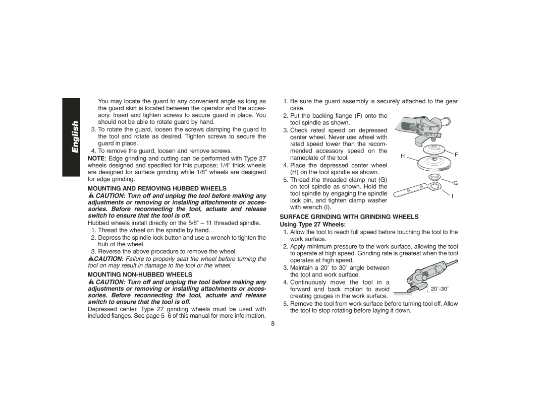
1.Be sure the guard assembly is securely attached to the gear case.
2.Put the backing flange (F) onto the
tool spindle as shown.
3. Check rated speed on depressed |
|
| |
center wheel. Never use wheel with |
|
| |
rated speed lower than the recom- |
|
| |
mended accessory speed on the | H | F | |
nameplate of the tool. | |||
| |||
4. Place the depressed center wheel |
|
| |
(H) on the tool spindle as shown. |
|
| |
5. Thread the threaded clamp nut (G) |
| G | |
on tool spindle as shown. Hold the |
| ||
|
| ||
tool spindle by engaging the spindle |
| I | |
lock pin, and tighten clamp washer |
| ||
|
| ||
with wrench (I). |
|
|
SURFACE GRINDING WITH GRINDING WHEELS Using Type 27 Wheels:
1.Allow the tool to reach full speed before touching the tool to the work surface.
2.Apply minimum pressure to the work surface, allowing the tool to operate at high speed. Grinding rate is greatest when the tool operates at high speed.
3. Maintain a 20˚ to 30˚ angle between the tool and work surface.
4. Continuously move the tool in a |
|
forward and back motion to avoid | |
creating gouges in the work surface. |
|
5.Remove the tool from work surface before turning tool off. Allow the tool to stop rotating before laying it down.