FIG. 1 |
| A | |||||||||||||||
C |
|
|
|
|
|
|
|
|
|
|
|
|
|
|
|
| H |
|
|
|
|
|
|
|
|
|
|
|
|
|
|
|
|
| |
|
|
|
|
|
| G |
|
|
|
|
|
|
|
| |||
|
|
|
|
|
|
|
| ||||||||||
|
|
|
|
|
|
|
|
|
|
|
|
|
|
|
| ||
| J |
|
|
|
|
|
|
|
|
|
|
| D | ||||
|
|
|
|
|
|
|
|
|
|
|
|
|
|
| |||
|
|
|
|
|
|
|
|
|
|
|
|
|
|
|
|
| |
|
|
|
| F |
|
|
|
|
|
|
|
|
|
|
|
| |
|
|
| B |
|
|
|
|
|
|
|
|
|
|
|
|
| |
|
|
|
|
|
| ||||||||||||
|
|
|
|
|
|
|
|
|
|
|
|
|
|
|
| ||
|
|
|
|
|
|
|
|
|
|
|
| E | |||||
|
|
|
|
|
|
|
|
|
|
|
|
|
|
|
| ||
|
|
|
|
|
|
|
|
|
|
|
|
|
|
|
|
|
|
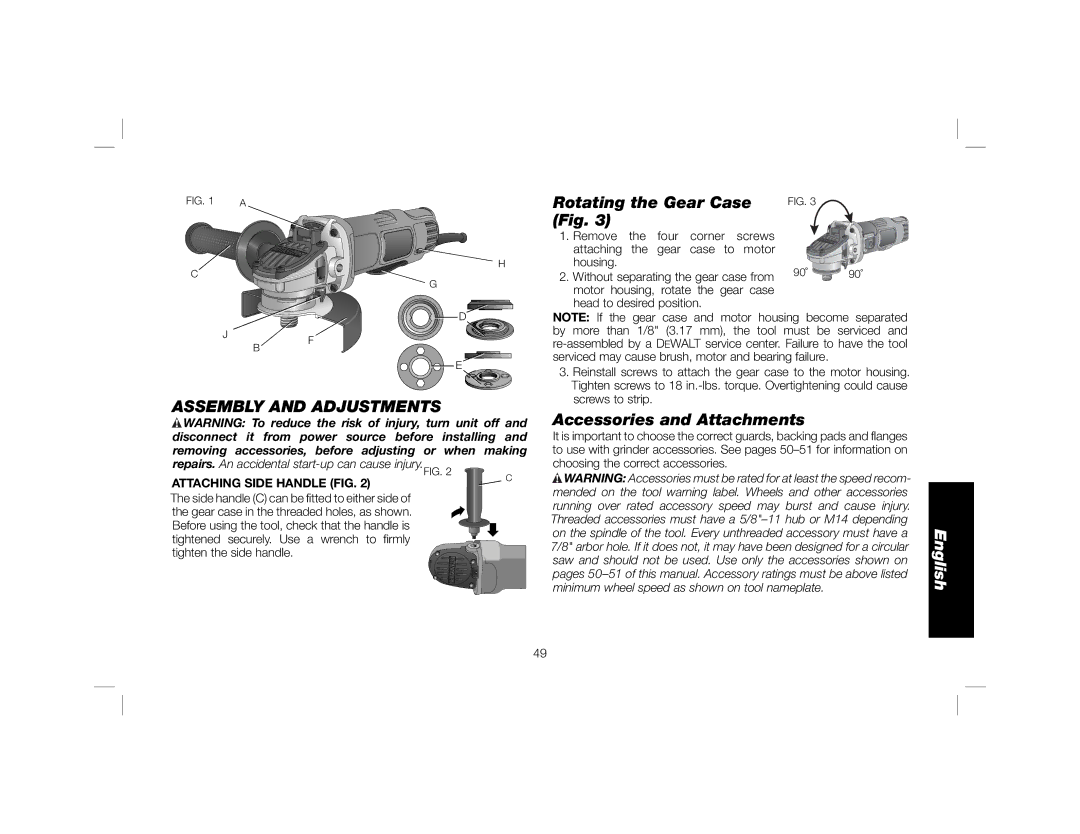
ASSEMBLY AND ADJUSTMENTS
![]() WARNING: To reduce the risk of injury, turn unit off and disconnect it from power source before installing and removing accessories, before adjusting or when making
WARNING: To reduce the risk of injury, turn unit off and disconnect it from power source before installing and removing accessories, before adjusting or when making
repairs. An accidental | C | |
ATTACHING SIDE HANDLE (FIG. 2) | ||
|
The side handle (C) can be fitted to either side of the gear case in the threaded holes, as shown. Before using the tool, check that the handle is tightened securely. Use a wrench to firmly tighten the side handle.
Rotating the Gear Case | FIG. 3 |
| |
(Fig. 3) |
|
| |
1. | Remove the four corner screws |
|
|
| attaching the gear case to motor |
|
|
| housing. | 90˚ | 90˚ |
2. | Without separating the gear case from | ||
motor housing, rotate the gear case head to desired position.
NOTE: If the gear case and motor housing become separated by more than 1/8" (3.17 mm), the tool must be serviced and
3.Reinstall screws to attach the gear case to the motor housing. Tighten screws to 18
Accessories and Attachments
It is important to choose the correct guards, backing pads and flanges to use with grinder accessories. See pages
![]() WARNING: Accessories must be rated for at least the speed recom- mended on the tool warning label. Wheels and other accessories running over rated accessory speed may burst and cause injury. Threaded accessories must have a
WARNING: Accessories must be rated for at least the speed recom- mended on the tool warning label. Wheels and other accessories running over rated accessory speed may burst and cause injury. Threaded accessories must have a
49