Grounded |
Wrist Strap |
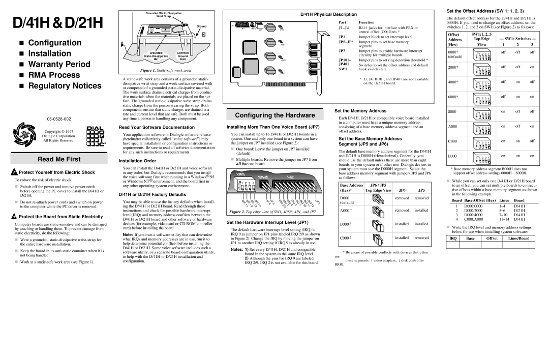
D/41H Physical Description
Set the Offset Address (SW 1: 1, 2, 3)
D/41H &D/21H
nConfiguration
nInstallation
nWarranty Period
nRMA Process
nRegulatory Notices
| Ground |
Grounded | Common |
Ground | |
Mat | Point |
Figure 1. | |
A
JP7![]()
![]()
![]()
![]()
![]()
![]()
![]()
![]()
![]()
![]()
JP 1 JP5/ 6
S W1
JP 101 |
|
JP 201 | J1 |
| J2 |
JP301
J3
![]() J4 JP401
J4 JP401
Part | Function |
| central office (CO) lines * |
JP1 | Jumper block to set interrupt level |
Jumper pins to set base memory | |
| segment |
JP7 | Jumper pins to enable hardware interrupt |
| circuitry for multiple boards |
JP101– | Jumper pins to set ring detection threshold * |
JP401 | Switches to set the offset address and default |
SW1 | hook switch state |
*J3, J4, JP301, and JP401 are not available on the D/21H board.
The default offset address for the D/41H and D/21H is 0000H. If you need to change an offset address, set the switches 1, 2, and 3 on SW1 (see Figure 2) as follows:
Offset | SW1:1, 2, 3 |
|
|
|
Address | Top Edge | — SW1: Switches — | ||
(Hex) | View | 1 | 2 | 3 |
0000* | 1 | 2 | 3 | 4 | off | off | off |
(default) |
|
|
| ||||
|
|
|
|
|
|
| |
2000* | 1 | 2 | 3 | 4 | off | off | on |
4000* | 1 | 2 | 3 | 4 | off | on | off |
6000* | 1 | 2 | 3 | 4 | off | on | on |
Copyright © 1997
Dialogic Corporation.
All Rights Reserved.
Read Me First
 Protect Yourself from Electric Shock
To reduce the risk of electric shock:
nSwitch off the power and remove power cords before opening the PC cover to install the D/41H or D/21H.
nDo not
 Protect the Board from Static Electricity
Computer boards are
nWear a grounded,
nKeep the board in its
nWork at a
components ensure that static charges are drained at a rate and current level that are safe. Both must be used any time a person is handling any component.
Read Your Software Documentation
Your application software or Dialogic software release (hereinafter collectively called “voice software”) may have special installation or configuration instructions or requirements. Be sure to read all software documentation for any such instructions or requirements.
Installation Order
You can install the D/41H or D/21H and voice software in any order, but Dialogic recommends that you install the voice software first when running in a Windows® 95 or Windows NT® environment, and the board first in any other operating system environment.
D/41H or D/21H Factory Defaults
You may be able to use the factory defaults when install- ing the D/41H or D/21H board. Read through these instructions and check for possible hardware interrupt level (IRQ) and memory address conflicts between the D/41H or D/21H board and other software or hardware devices (for example, video card or CD ROM controller card) before installing the board.
Note: If you own a software utility that can determine what IRQs and memory addresses are in use, run it to help determine potential conflicts before installing the D/41H or D/21H. Some voice software includes such a software utility, or a separate board configuration utility, to help with the D/41H or D/21H installation and configuration.
Configuring the Hardware
Installing More Than One Voice Board (JP7)
You can install up to 16 D/41H or D/21H boards in a system. One and only one board in a system can have the jumper on JP7 installed (see Figure 2):
nOne board: Leave the jumper on JP7 installed (default).
nMultiple boards: Remove the jumper on JP7 from all but one board.
1 | 2 | 3 | 4 |
|
|
|
|
|
|
| |
S S S S |
| J J | I I I I I I | I | I |
| J | ||||
W W W W | P P | R R R R R R R R |
| P | |||||||
6 5 | Q Q Q Q Q Q Q Q | 7 | |||||||||
| 1 1 1 | 1 | |||||||||
| 2 3 4 5 7 | 1 | 1 | 1 | |||||||
| : | : : | : |
|
| ||||||
| 1 2 3 | 4 |
| / | 0 | 1 | 2 |
| |||
|
|
| 9 |
|
|
|
| ||||
Figure 2. Top edge view of SW1, JP5/6, JP1, and JP7 | |||||||||||
Set the Hardware Interrupt Level (JP1)
The default hardware interrupt level setting (IRQ) is IRQ 9 (a jumper on JP1 pins labeled IRQ 2/9 as shown in Figure 2). Change the IRQ by moving the jumper on JP1 to another IRQ setting if IRQ 9 is already in use.
Notes: 1) Set every D/41H, D/21H and compatible board in the system to the same IRQ level.
2)Although the pins for IRQ 9 are labeled IRQ 2/9, IRQ 2 is not available for this board.
Set the Memory Address
Each D/41H, D/21H or compatible voice board installed in a computer must have a unique memory address consisting of a base memory address segment and an offset address.
Set the Base Memory Address
Segment (JP5 and JP6)
The default base memory address segment for the D/41H and D/21H is D000H (Hexadecimal). Generally, you should use the default unless there are more than eight boards in your system or if other
Base Address | JP6 / JP5 |
|
|
(Hex)* | Top Edge View | JP6 | JP5 |
D000 |
| removed | removed |
(default) |
|
|
|
A000 † |
| removed | installed |
B000 † |
| installed | installed |
C000 ‡ |
| installed | removed |
* Be aware of possible conflicts with devices that often
use
these segments: † video adapters; ‡ disk controller
BIOS.
8000 | 1 | 2 | 3 | 4 | on | off | off |
A000 | 1 | 2 | 3 | 4 | on | off | on |
C000 | 1 | 2 | 3 | 4 | on | on | off |
E000 | 1 | 2 | 3 | 4 | on | on | on |
*Base memory address segment B000H does not support offset address settings 0000H – 6000H.
nWhile you can set only one D/41H or D/21H board to an offset, you can set multiple boards to consecu- tive offsets within a base memory segment as shown in the following example.
Board | Base:Offset (Hex) | Lines | Board |
1 | D000:0000 | D/41H | |
2 | D000:2000 | D/21H | |
3 | D000:4000 | D/41H | |
4 | C000:A000 | D/41H |
nWrite the IRQ level and memory address settings below for use when installing system software:
IRQ | Base | Offset | Lines/Board |
|
|
|
|