Dialogic®
VFX/41JCT-LS
Media Board
| Part Number |
| Copyright © |
| Dialogic Corporation. |
. | All Rights Reserved |
|
1. Protect Boards from Damage
![]() Caution! All computer boards are sensitive to electrostatic discharge (“ESD”). Handle all static- sensitive boards and components at a
Caution! All computer boards are sensitive to electrostatic discharge (“ESD”). Handle all static- sensitive boards and components at a
If you are not familiar with ESD safety precautions, visit http://www.dialogic.com/support/hwinstall to learn more.
Unpacking the Board
Unpack the Dialogic®
1. | Prepare a |
2. | Carefully remove the board from the shipping |
| carton and |
| board by the edges and avoid touching the |
A. Set the Board ID Number
When you start Dialogic® boards, each board is assigned a sequential number for identification and use by the system software. This sequential number specifies the device and channel name(s) for each board. The board number is based on the board ID that you set using the SW30 rotary switch on the board.
Use the SW30 rotary switch to specify board sequencing as follows:
Automatic Assignment: Board ID 0
Also called geographical method. All Dialogic® PCI boards can share the factory default setting of board ID 0. In this case, boards are automatically sorted by PCI bus and slot number.
Note: Adding or removing a board can cause the renumbering of boards in the system. Consequently, the assignment of device names may change during the next system
Manual Assignment: Board IDs
In addition to the automatic assignment method, you can use the manual or discrete assignment method to further identify boards in your system.
If you change the board ID from the factory default of 0 to any other number, the software will use that setting to identify the board.
Note: When not set to 0, the board ID must be unique. It must not conflict with the board ID of any other Dialogic® ISA or PCI board. If you use this method, we recommend that you assign sequential numbers starting at 1. This method is also used for all ISA bus boards.
Note: The Dialogic® software can correctly register your boards for proper operation; however, due to variations among computer chassis, it is not possible for the software to determine where each board is physically placed. For more information on board ID numbering issues, see the Dialogic® Installation and Configuration Guide for your operating system or visit the Dialogic Technical Support website at
http:/www.dialogic.com/support/helpweb/.
B.Set the Hook-Switch State for Start-Up (Optional)
Set the SW4 switch as follows to select how the board responds to an incoming call when the computer power is on but the board is not initialized.
|
| SW4 | |
Ringing | |||
| OFF | ||
|
SW4 = Off (default): Callers hear ringing
Busy |
| SW4 |
| ||
|
| ON |
|
SW4 = On: Callers hear a busy signal
Note: If the computer power is off, callers hear ringing
3. Set CT Bus Jumpers (optional)
The Computer Telephony bus (CT Bus) provides communication and flexible resource sharing among the boards connected to the bus. This Dialogic® board has a CT Bus connector that complies with the ECTF H.100 specification, and as such can be connected to the
Note: If these boards are operating in SCbus mode, CT Bus (H.100) termination is not required.
The following instructions only apply to the boards at each end of the CT Bus cable. Only boards at each end of the CT Bus cable must be terminated.
JP1 jumper is reserved and unused. DO NOT install a shunt across the pins of JP1.
JP2 is a
To use the CT Bus:
Install the shunt on the JP2 jumper of a board to terminate the CT Bus at that board.
Only terminate the first and last boards (the boards located at each end) on the CT Bus cable.
Do not install a shunt across the pins of JP2 on boards located between the end boards on the CT Bus cable (the shunt must be disconnected on the JP2 jumper to disable termination).
The JP2 jumper terminates the H.100 signals listed in the following table.
Shunt | H.100 signal terminated |
JP2, Pins 1 and 2 (used | CT_FRAME_(A&B) |
on boards at each end of | CT_C8_(A&B) |
CT Bus cable only) |
|
4. Install the Board
![]() Warning! To reduce the risk of electric shock: Switch off the power and disconnect all power cords.
Warning! To reduce the risk of electric shock: Switch off the power and disconnect all power cords.
Do not
Install the board in the computer chassis according to the following instructions:
1.Remove the computer cover.
2.Select an empty PCI bus slot, and remove the slot’s retaining screw and access coverplate.
Retaining Screw ![]()
![]()
Metal Coverplate for Slot ![]()
Note: If you are not installing your board in an ISA
board’s components. |
Numbering Precedence in Mixed Systems
CT Bus with a CT Bus cable.
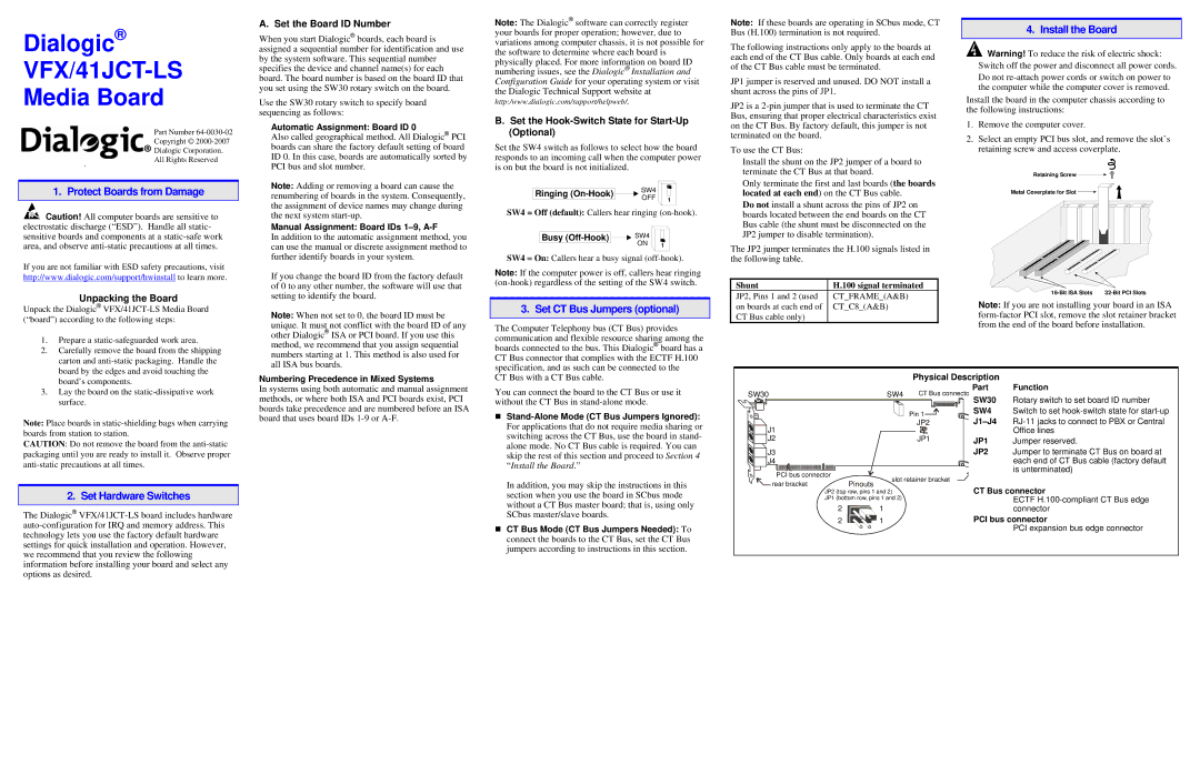
Physical Description
3. Lay the board on the |
surface. |
Note: Place boards in
CAUTION: Do not remove the board from the
2. Set Hardware Switches
The Dialogic®
In systems using both automatic and manual assignment methods, or where both ISA and PCI boards exist, PCI boards take precedence and are numbered before an ISA board that uses board IDs
You can connect the board to the CT Bus or use it without the CT Bus in
For applications that do not require media sharing or switching across the CT Bus, use the board in stand- alone mode. No CT Bus cable is required. You can skip the rest of this section and proceed to Section 4 “Install the Board.”
In addition, you may skip the instructions in this section when you use the board in SCbus mode without a CT Bus master board; that is, using only SCbus master/slave boards.
CT Bus Mode (CT Bus Jumpers Needed): To connect the boards to the CT Bus, set the CT Bus jumpers according to instructions in this section.
SW30 |
|
| SW4 | CT Bus connecto |
|
|
|
| Pin 1 |
J1 |
|
|
| JP2 |
|
|
|
| |
J2 |
|
|
| JP1 |
J3 |
|
|
|
|
J4 |
|
|
|
|
| PCI bus connector | slot retainer bracket | ||
rear bracket |
| |||
JP2 (top row, pins 1 and 2) |
| |||
|
|
| ||
|
| JP1 (bottom row, pins 1 and 2) |
| |
2![]()
![]()
![]()
![]()
![]() 1
1
2![]()
![]()
![]() 1
1
Part Function
SW30 Rotary switch to set board ID number
SW4 Switch to set
JP1 Jumper reserved.
JP2 Jumper to terminate CT Bus on board at each end of CT Bus cable (factory default is unterminated)
CT Bus connector
ECTF
PCI bus connector
PCI expansion bus edge connector