Install Guide
MDI - X/MDI Switch
The
•For a hub/repeater, use a swap cable (pins are connected 1 to 3, 2 to 6, 3 to 1, and 6 to 2)
•For a workstation/PC, use a
![]()
![]()
![]() 4
4
![]() 3
3
![]()
![]() 2
2 ![]() 1
1
LEDs | |
Connector | (4 total) |
Switch
Connectors
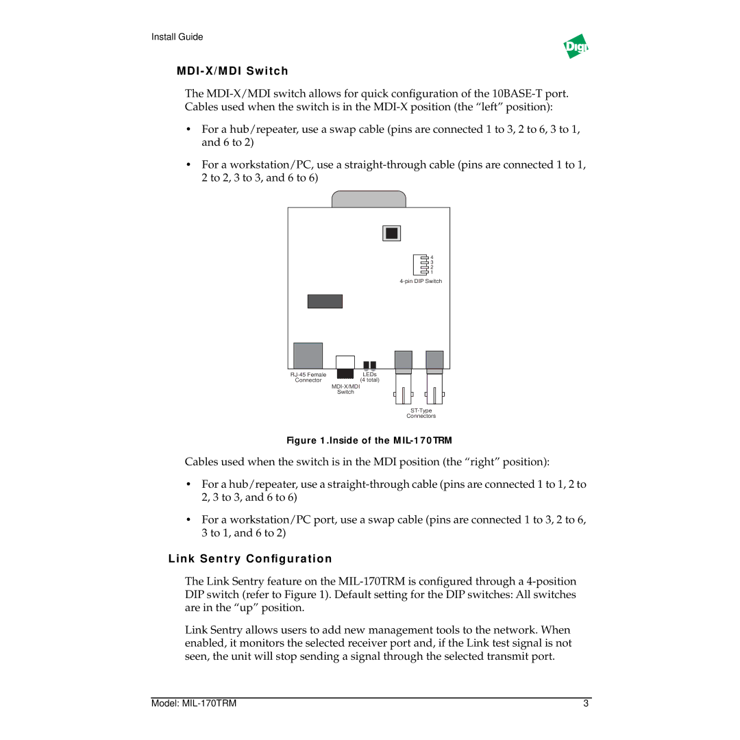
Figure 1.Inside of the MIL-170TRM
Cables used when the switch is in the MDI position (the “right” position):
•For a hub/repeater, use a
•For a workstation/PC port, use a swap cable (pins are connected 1 to 3, 2 to 6, 3 to 1, and 6 to 2)
Link Sentr y Configuration
The Link Sentry feature on the
Link Sentry allows users to add new management tools to the network. When enabled, it monitors the selected receiver port and, if the Link test signal is not seen, the unit will stop sending a signal through the selected transmit port.
Model: | 3 |