WR44 Series Installation Guide
ANT. WLAN | This male SMA connector is used to fit the wireless LAN diversity | |
(Aux.) | antenna for improved receiver sensitivity. | |
(Models with WLAN option fitted only) | ||
| ||
|
| |
LAN 0, 1, 2, 3 | The socket labelled LAN is used to connect the unit to a | |
| ||
| Pair) cable supplied or a suitable alternative. This port is auto- | |
| sensing for speed and wiring | |
| comply with EMC requirements it should not be used with non- | |
| STP cable. | |
|
|
Reset button
This is located on the underside of the unit near the front (just behind the DTE LED), and can be accessed through a 2.5mm hole using pencil tip or similar implement. Holding the reset button down gently for 5 seconds when the unit is powered up and operational (i.e. has finished booting), will cause the factory settings to be loaded into flash before and then
1.3Optional features.
WR44 series routers are available with a variety of hardware options. At present these are:
1 x ASY | Provides an additional asynchronous serial port using a |
| connector |
|
|
3 x ASY | Provides three additional asynchronous serial ports using RJ45 |
| connectors. |
1 x SYN | Provides an X.21/RS422/RS232 synchronous serial port using a |
| |
1 x GPS | Provides GPS |
|
|
1 x ISDN BRI | Provides an ISDN Basic Rate Interface (BRI) via an RJ45 socket. |
| This can be configured either as a TE (terminal endpoint) or as |
| |
| asynchronous serial port via a second RJ45 socket. |
|
|
Telemetry 1 | General Digital I/O Card. |
Card |
|
WR44 Series Installation Guide
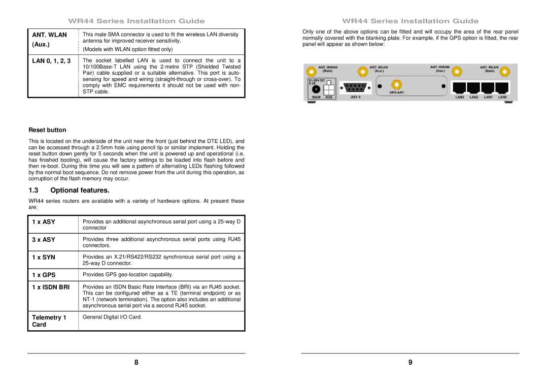
Only one of the above options can be fitted and will occupy the area of the rear panel normally covered with the blanking plate. For example, if the GPS option is fitted, the rear panel will appear as shown below:
8 | 9 |