WR44 Series Installation Guide
NET | Illuminates steady | when a wireless data connection has been | |
| established. |
| |
|
| ||
SIM | Illuminates steady when a valid SIM card is installed in the unit. | ||
|
| ||
DAT | Flashes to indicate that data is being transferred over the wireless | ||
| network. |
| |
SIGNAL | The three indicators labelled SIGNAL illuminate to indicate the | ||
| GSM signal strength as follows: | ||
| None illuminated | < | |
| 1 | LED illuminated | >= |
| 2 | LED’s illuminated | >= |
| 3 | LED’s illuminated | >= |
|
|
|
|
SIM Sockets
The two sockets at the right side of the front panel labelled SIM 1 and SIM 2 are for use with the Subscriber Identification Module(s) (SIMs) that you will receive from your service provider(s).
Details of how to insert SIM cards correctly are given in section 2 below.
WR44 Series Installation Guide
1.2Rear Panel Features
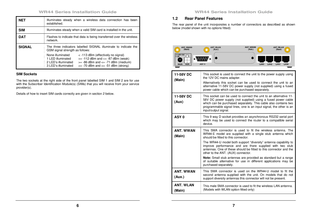
The rear panel of the unit incorporates a number of connectors as described as shown below (model shown with no options fitted):
This socket is used to connect the unit to the power supply using | ||
(Main) | the 12V DC mains adapter. | |
Alternatively this socket can be used to connect the unit to an | ||
| ||
| alternative | |
| power cable which can be purchased separately. | |
|
| |
This socket can be used to connect the unit to an alternative 11- | ||
(Aux) | 58V DC power supply (not supplied) using a fused power cable | |
which can be purchased separately. This cable also contains two | ||
| programmable signal lines, one is an input signal, the other is an | |
| input/output signal. | |
|
| |
ASY 0 | This 9 way D socket provides an asynchronous RS232 serial port | |
| which may be used to connect the router to a compatible serial | |
| device. | |
|
| |
ANT. WWAN | This SMA connector is used to fit the wireless antenna. The | |
(Main) | ||
should be fitted to this connector. | ||
| The | |
| improve performance and are there supplied with two stub | |
| antennas. One of these should be fitted to this connector and the | |
| other to the ANT. (AUX) connector. | |
| Note: Small stub antennas are provided as standard but a range | |
| of suitable alternative for use in different applications may be | |
| purchased separately. | |
|
| |
ANT. WWAN | This SMA connector is used on the | |
(Aux.) | second antenna supplied with the unit. On models that do not | |
support diversity antennas this connector will not be present. | ||
|
| |
ANT. WLAN | This male SMA connector is used to fit the wireless LAN antenna. | |
(Main) | (Models with WLAN option fitted only) | |
|
|
6 | 7 |