Manuals
/
Directed Video
/
Computer Equipment
/
Network Card
Directed Video
GM100
manual
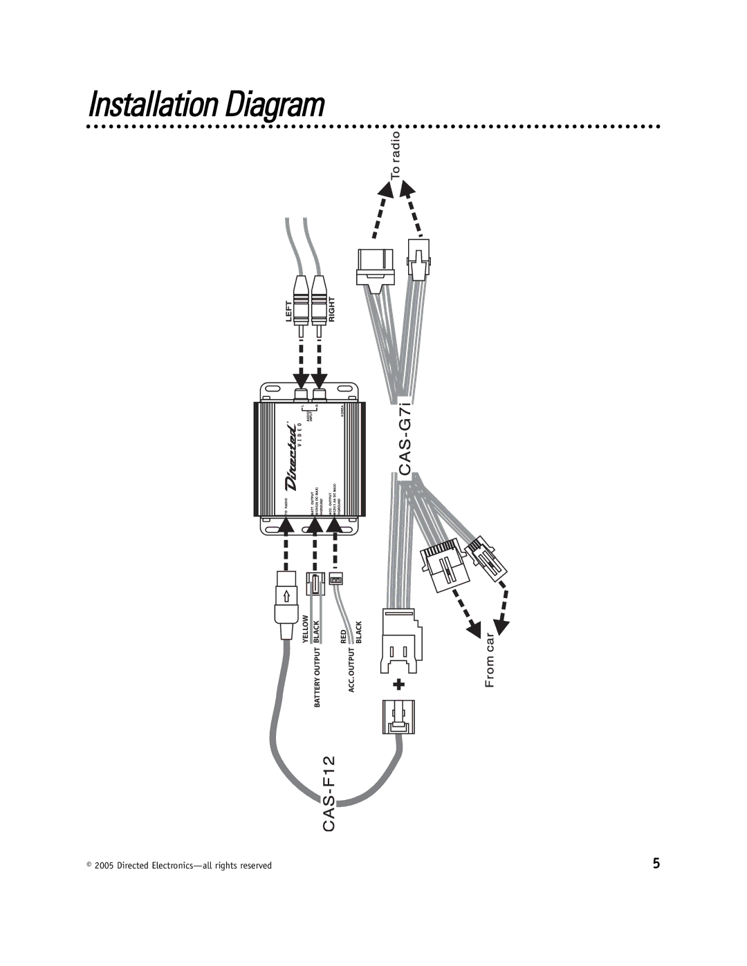
Installation Diagram
Models:
GM100
1
5
8
8
Download
8 pages
32.76 Kb
1
2
3
4
5
6
7
8
Install
Page 5
Image 5
Installation Diagram
YELLOW
BATTERY OUTPUT BLACK
RED
BLACK
ACC. OUTPUT
© 2005 Directed
Electronics—all
rights reserved
5
Page 4
Page 6
Page 5
Image 5
Page 4
Page 6
Contents
GM100 GM OE Interface to RSE Port
Non-Transferable Limited Consumer Warranty
What’s Included
Table of Contents
Introduction
Applications
Installation
Refer to the Installation Diagram below
Installation Diagram
Choke Installation Diagram
Option
Operation
Company behind this system is Directed Electronics
Top
Page
Image
Contents