6
Black male pin plug (12 pin)
To
Flat
male pin plug (24 pin)
From car
CAS-G7i
Yellow wire
Red wire
OUT
CHOKE
FILTER
IN
Red wire
Yellow wire
Black male pin plug (12 pin)
Black wire
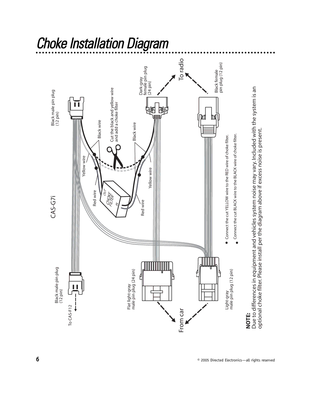
Cut the black and yellow wire and add a choke filter
Black wire
To radio
Choke Installation Diagram
© 2005 Directed Electronics—
Light-gray
male pin plug (12 pin)
Black female pin plug (12 pin)
Connect the cut YELLOW wire to the RED wire of choke filter.
Connect the cut BLACK wire to the BLACK wire of choke filter.
all rights reserved
NOTE:
Due to differences in equipment and vehicles system noise may vary. Included with the system is an optional choke filter. Please install per the diagram above if excess noise is present.