3-1
SECTION 3
INSTALLATION
3.1Control unit and Suppressor Frames
The installation of Model 430 series consists of plugging together the component parts and rack mounting (prefereably) the control unit and each two-channel frame. Taking a typical system with three channels, the procedure is as follows:
The system should be unpacked and inspected for damage. Any damage should be reported to the carrier and distributor immediately.
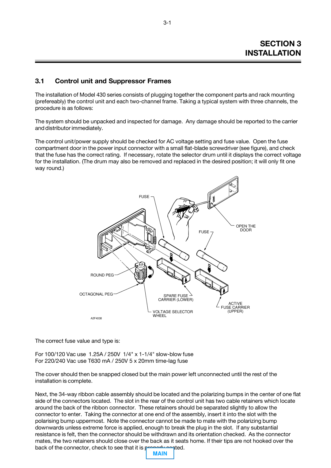
The control unit/power supply should be checked for AC voltage setting and fuse value. Open the fuse compartment door in the power input connector with a small flat-blade screwdriver (see figure), and check that the fuse has the correct rating. If necessary, rotate the selector drum until it displays the correct voltage for the installation. (The drum may also be removed and replaced in the desired position; it will only fit one way round.)
FUSE
OPEN THE
FUSEDOOR
ROUND PEG | |
OCTAGONAL PEG | SPARE FUSE |
|
| CARRIER (LOWER) |
ACTIVE
FUSE CARRIER
VOLTAGE SELECTOR(UPPER)
WHEEL
A2F4038
The correct fuse value and type is:
For 100/120 Vac use 1.25A / 250V 1/4" x 1-1/4" slow-blow fuse
For 220/240 Vac use T630 mA / 250V 5 x 20mm time-lag fuse
The cover should then be snapped closed but the main power left unconnected until the rest of the installation is complete.
Next, the 34-way ribbon cable assembly should be located and the polarizing bumps in the center of one flat side of the connectors located. The slot in the rear of the control unit has two cable retainers which locate around the back of the ribbon connector. These retainers should be separated slightly to allow the connector to enter. Taking the connector at one end of the assembly, insert it into the slot with the polarising bump uppermost. Note the connector cannot be made to mate with the polarizing bump downwards unless extreme force is applied, enough to break the plug in the slot. If any substantial resistance is felt, then the connector should be withdrawn and its orientation checked. As the connector mates, the two retainers should close over the back as it seats home. If their tips are not hooked over the back of the connector, check to see that it is properly seated.
MAIN

