2-1
SECTION 2
OPERATION
2.1CONTROLS
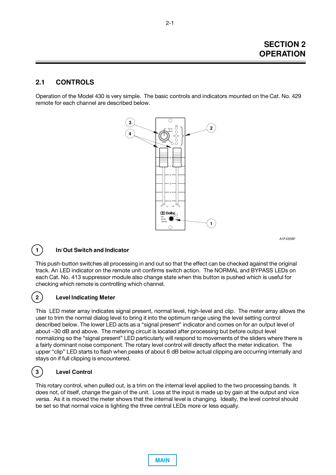
Operation of the Model 430 is very simple. The basic controls and indicators mounted on the Cat. No. 429 remote for each channel are described below.
2
3
4
5
LF HF
Dolby
430in
Series
Remote
1 In/Out Switch and Indicator
This push-button switches all processing in and out so that the effect can be checked against the original track. An LED indicator on the remote unit confirms switch action. The NORMAL and BYPASS LEDs on each Cat. No. 413 suppressor module also change state when this button is pushed which is useful for checking which remote is controlling which channel.
2 Level Indicating Meter
This LED meter array indicates signal present, normal level, high-level and clip. The meter array allows the user to trim the normal dialog level to bring it into the optimum range using the level setting control described below. The lower LED acts as a “signal present” indicator and comes on for an output level of about –30 dB and above. The metering circuit is located after processing but before output level normalizing so the “signal present” LED particularly will respond to movements of the sliders where there is a fairly dominant noise component. The rotary level control will directly affect the meter indication. The upper “clip” LED starts to flash when peaks of about 6 dB below actual clipping are occurring internally and stays on if full clipping is encountered.
3 Level Control
This rotary control, when pulled out, is a trim on the internal level applied to the two processing bands. It does not, of itself, change the gain of the unit. Loss at the input is made up by gain at the output and vice versa. As it is moved the meter shows that the internal level is changing. Ideally, the level control should be set so that normal voice is lighting the three central LEDs more or less equally.

![]()
