DP571, DP572 specifications
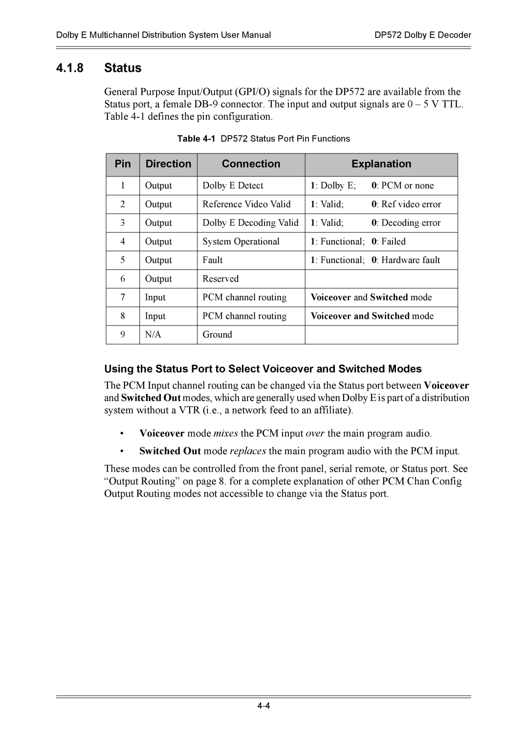
Dolby Laboratories has long been a pioneer in audio and video technology, continuously pushing the boundaries of entertainment experiences. Among their range of innovative products, the Dolby DP572 and DP571 audio processors stand out as powerful tools for commercial cinema and installation applications. These devices are designed to enhance the overall sound experience in theaters, auditoriums, and other large venues, making them crucial for delivering high-quality audio.The Dolby DP572 is a multi-channel audio processor that supports 7.1 surround sound configurations. It is equipped with advanced Dolby technologies, including Dolby Digital, Dolby Digital Plus, and Dolby TrueHD. This versatility allows filmmakers and sound engineers to create immersive soundscapes that bring an added layer of realism to the viewer's experience. One of the salient features of the DP572 is its advanced processing capabilities, which include automatic calibration, loudness control, and extensive equalization options, ensuring that the sound quality is optimized for any environment.
On the other hand, the Dolby DP571 is a companion processor designed primarily for applications that require flexible audio routing and management. It features the same high-quality audio processing as the DP572 but focuses more on signal management, making it ideal for venues that may need to adapt their audio setup frequently. The DP571 supports both analog and digital audio inputs and outputs, providing versatility for various sound systems. Both units feature user-friendly interfaces, making them accessible for system integrators and operators alike.
In terms of connectivity, both processors boast multiple inputs and outputs, allowing seamless integration with existing audio systems and peripherals. They also support industry-standard audio formats, making them compatible with a wide range of content sources. Signature Dolby technologies, such as dialogue enhancement and surround sound synthesis, ensure that even the most complex audio tracks are rendered with precision.
In summary, the Dolby DP572 and DP571 audio processors are essential components for any cinema or professional audio setup. Their advanced features, compatibility with multiple audio formats, and the legendary sound quality synonymous with Dolby make them invaluable tools for creating immersive audio experiences that captivate audiences. Whether used in conjunction or independently, these processors deliver the high-fidelity sound that is key to modern entertainment.
