| 1 |
| 2 |
| 3 |
| 4 |
|
|
|
|
|
|
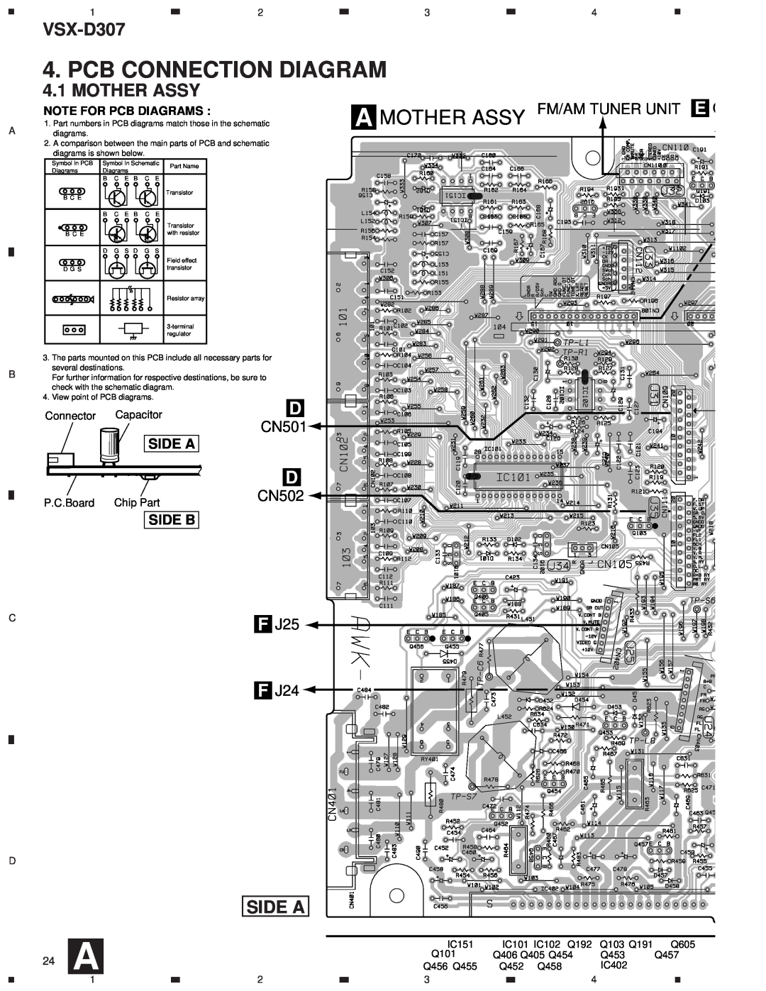
4. PCB CONNECTION DIAGRAM
4.1 MOTHER ASSY
NOTE FOR PCB DIAGRAMS :
1. Part numbers in PCB diagrams match those in the schematic
Adiagrams.
2.A comparison between the main parts of PCB and schematic diagrams is shown below.
Symbol In PCB | Symbol In Schematic | Part Name | |
Diagrams | Diagrams | ||
| |||
| B C E B C E |
| |
B C E |
| Transistor | |
|
| ||
| B C E B C E |
| |
|
| Transistor | |
B C E |
| with resistor | |
| D G S D G S |
| |
|
| Field effect | |
D G S |
| transistor | |
|
| Resistor array | |
|
| ||
|
| regulator |
A MOTHER ASSY FM/AM TUNER UNIT | E | C |
|
3.The parts mounted on this PCB include all necessary parts for several destinations.
BFor further information for respective destinations, be sure to check with the schematic diagram.
4.View point of PCB diagrams.
Connector | Capacitor | D |
|
|
|
|
| |
CN501 |
|
|
|
|
| |||
|
|
|
|
|
|
|
| |
|
| SIDE A |
|
|
|
|
|
|
|
|
| D |
|
|
|
|
|
P.C.Board | Chip Part | CN502 |
|
|
|
|
| |
|
|
|
|
|
| |||
|
| SIDE B |
|
|
|
|
|
|
C |
|
| F J25 |
|
|
|
|
|
|
|
|
|
|
|
|
| |
|
|
| F J24 |
|
|
|
|
|
D |
|
|
|
|
|
|
|
|
|
|
| SIDE A |
|
|
|
|
|
| A |
|
| IC151 | IC101 IC102 | Q192 | Q103 Q191 | Q605 |
24 |
|
| Q101 | Q406 Q405 Q454 | Q453 | Q457 | ||
|
| Q456 Q455 | Q452 Q458 |
| IC402 |
| ||
| 1 |
| 2 | 3 |
| 4 |
|
|