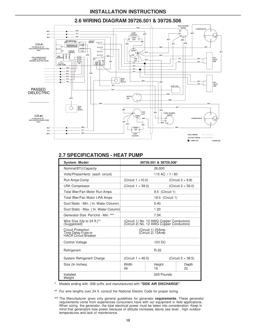
39626.506, 39726.501, 39626.501, 39726.506 specifications
The Dometic 39726.506, 39626.501, 39726.501, and 39626.506 are versatile and well-engineered products designed to enhance the comfort and convenience of outdoor enthusiasts and travelers. These models are primarily known for their compatibility with various vehicle types, including RVs, campers, and trailers, making them essential for anyone seeking a reliable solution for food storage and cooking on the go.One of the standout features of the Dometic models is their impressive energy efficiency. Equipped with advanced insulation technology, these units maintain optimal temperatures while consuming minimal power. This is particularly advantageous for users who rely on battery power during extended trips. The energy-efficient design not only supports eco-friendly practices but also extends the life of the battery, allowing for longer excursions without the need for frequent recharges.
The Dometic 39726.506 and 39626.501 models boast a large capacity, offering ample space to store a variety of food and beverages. With adjustable shelves and compartments, users can customize the interior layout to accommodate their specific needs, ensuring efficient organization and easy access to items. The user-friendly interface allows for simple temperature adjustments, making it easy to set the ideal environment for perishable goods.
In terms of durability, Dometic products are constructed with high-quality materials designed to withstand the rigors of outdoor use. The exterior is often reinforced to resist impact and weather conditions, which is crucial for adventures in diverse environments. The seals and hinges are also designed to prevent leaks, ensuring that stored items remain safe and secure during transport.
For ease of use, many models come equipped with built-in diagnostics and alerts that notify users of any performance issues. This technology enhances reliability and allows for timely maintenance, reducing the likelihood of unexpected failures while on the road. Additionally, these Dometic models often feature user-friendly controls, enabling hassle-free operation even for those unfamiliar with similar appliances.
Overall, the Dometic 39726.506, 39626.501, 39726.501, and 39626.506 models combine efficiency, durability, and convenience, making them exemplary choices for culinary needs during travel. As part of the brand's commitment to quality, these products not only meet user expectations but often exceed them, ensuring a positive experience for adventurers looking to enjoy fresh and delicious meals in the great outdoors.

