lo. Removing the air pump and replacing the piston.
__________________ _____
1.Unscrew knob (A, Fig.9) of air pump (K, Fig.9) from the shaft (L, Fig.9).
2.Unscrew air pump ( 4 screws / M, Fig. 9).
3.Unscrew cover of
4.Withdraw shaft, force out retaining disc from the groove, pull off large disc and change joint ring.
5.Reassemble in the reverse order.
CAUTION: After all repairs to the gas equipment, the entire gas system must be checked for leaks with soapy solution.
NEVER USE A MATCH
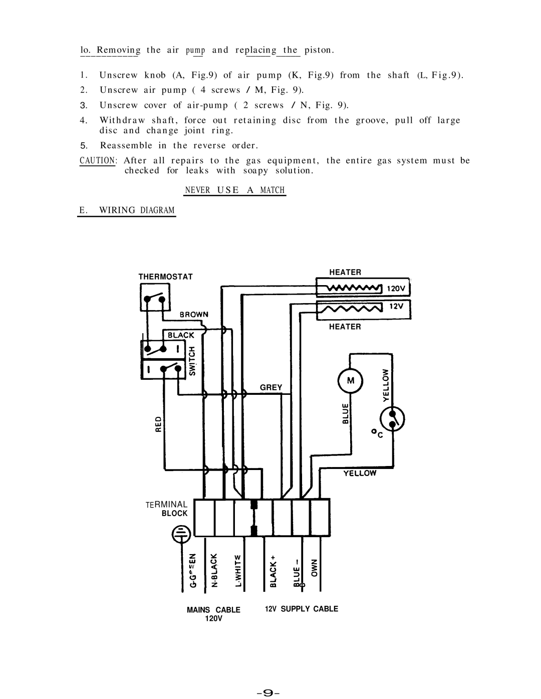
E.WIRING DIAGRAM
THERMOSTAT
GREY
HEATER
1
HEATER
1
TERMINAL
BLOCK
y w
5 0
W 5 5 a
s t$$i
P
MAINS CABLE
120V
+
4 g
z
iii
12V SUPPLY CABLE
