free of soot. Heavy soot formation indicates improper functioning of the burner. The flue and burner both require cleaning in the following manner:
1)Unplug the refrigerator power cord from the 120 volt AC outlet (see FIG. 6).
2)Disconnect or shut off the 12 volt power to the refrigerator.
3)Turn manual shutoff valve to OFF. (See FIG. 6 & 12).
4)Remove cover from the burner housing. (See FIG . 6).
5)Disconnect the wire from the high voltage electrode.
6)Remove the burner mounting screws and remove the burner assembly.
7)Remove the flue cap from top of flue tube and lift out the wire and spiral baffle. Clean the flue from the top using a flue brush. Blowing compressed air into the flue will not properly clean soot and scale out of the flue tube. Replace spiral baffle and flue cap.
8)Clean burner tube with a brush. Blow out burner with compressed air.
9)Before removing burner jet, clean burner area of soot and scale that fell out of flue tube. Remove the burner jet. Soak the jet in wood alcohol and allow it to air dry. Reinstall and tighten burner jet.
DO NOT use a wire or pin when cleaning the burner jet as damage can occur to the precision opening. This can cause damage to the refrigerator or create a fire hazard.
10)Reinstall burner, being careful that the end of the burner fits into the slot on the burner bracket. Check to make sure slots are centered under the flue tube and the thermocouple is positioned properly (tip of thermocouple extends over two slots of burner).
11)Be sure to reconnect the wire to high voltage elec- trode. Check the electrode for proper location and gap. (See FIG. 11).
FIG. 11 | ELECTRODE |
1/8" T O 3/16"
BURNER T UBE
12)Turn on manual gas shutoff valve and check all fittings for leaks.
13)Connect 120 volt power cord to the outlet and reconnect or turn on the 12 volt DC power.
14)Check LP gas safety shutoff. See Section A. Instal- lation, Item 9. Testing LP Gas Safety Shutoff.
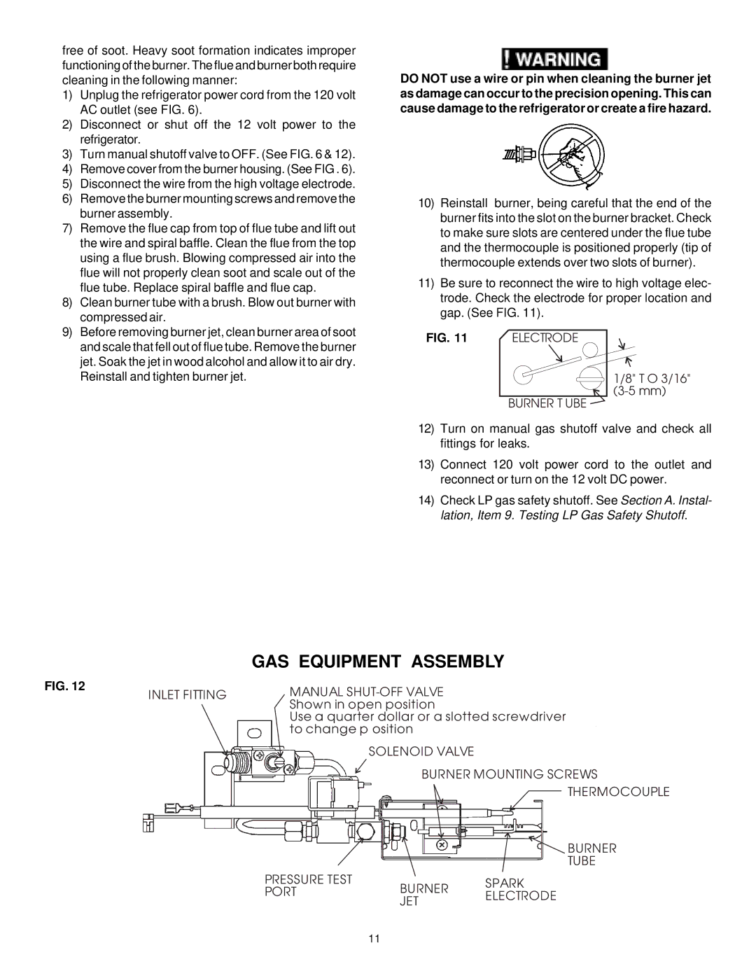
| GAS EQUIPMENT ASSEMBLY |
FIG. 12 | MANUAL |
INLET FITTING | |
| Shown in open position |
| Use a quarter dollar or a slotted screwdriver |
| to change p osition |
SOLENOID VALVE
BURNER MOUNTING SCREWS
THERMOCOUPLE
BURNER
TUBE
PRESSURE TEST | BURNER | SPARK | |
PORT | |||
ELECTRODE | |||
| JET | ||
|
|
11