220V Access by Draper
Motorized Roller/Fabric Installation
The bottom access panel must be removed fi rst.
The motor end mounting bracket has a metal bracket with snap ring for accepting motor head. Back out the four set screws in bracket until they are fl ush with top side of bracket.
page 2 of 4
220V & 12V VIDEO INTERFACE
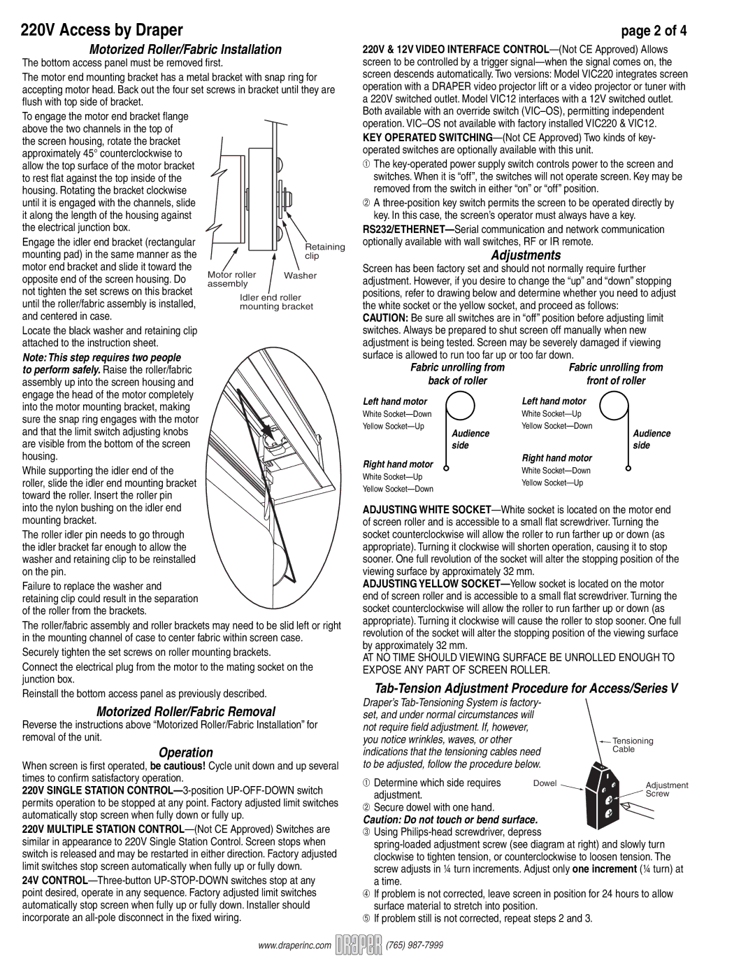
To engage the motor end bracket flange above the two channels in the top of the screen housing, rotate the bracket approximately 45° counterclockwise to allow the top surface of the motor bracket to rest fl at against the top inside of the housing. Rotating the bracket clockwise until it is engaged with the channels, slide it along the length of the housing against the electrical junction box.
Engage the idler end bracket (rectangular mounting pad) in the same manner as the motor end bracket and slide it toward the opposite end of the screen housing. Do not tighten the set screws on this bracket until the roller/fabric assembly is installed, and centered in case.
Locate the black washer and retaining clip attached to the instruction sheet.
Note: This step requires two people to perform safely. Raise the roller/fabric assembly up into the screen housing and engage the head of the motor completely into the motor mounting bracket, making sure the snap ring engages with the motor and that the limit switch adjusting knobs are visible from the bottom of the screen housing.
While supporting the idler end of the roller, slide the idler end mounting bracket toward the roller. Insert the roller pin into the nylon bushing on the idler end mounting bracket.
The roller idler pin needs to go through the idler bracket far enough to allow the washer and retaining clip to be reinstalled on the pin.
Failure to replace the washer and
retaining clip could result in the separation of the roller from the brackets.
| Retaining |
| clip |
Motor roller | Washer |
assembly |
|
Idler end roller mounting bracket
operation.
➀The
➁A
Adjustments
Screen has been factory set and should not normally require further adjustment. However, if you desire to change the “up” and “down” stopping positions, refer to drawing below and determine whether you need to adjust the white socket or the yellow socket, and proceed as follows:
CAUTION: Be sure all switches are in “off” position before adjusting limit switches. Always be prepared to shut screen off manually when new adjustment is being tested. Screen may be severely damaged if viewing surface is allowed to run too far up or too far down.
Fabric unrolling from | Fabric unrolling from | ||
back of roller | front of roller | ||
Left hand motor | Left hand motor | ||
White | White |
| |
Yellow | Yellow | Audience | |
Audience |
| ||
side |
| side | |
Right hand motor | Right hand motor |
| |
White | |||
White | |||
Yellow | |||
Yellow | |||
|
| ||
ADJUSTING WHITE
ADJUSTING YELLOW
The roller/fabric assembly and roller brackets may need to be slid left or right in the mounting channel of case to center fabric within screen case.
Securely tighten the set screws on roller mounting brackets.
Connect the electrical plug from the motor to the mating socket on the junction box.
Reinstall the bottom access panel as previously described.
Motorized Roller/Fabric Removal
Reverse the instructions above “Motorized Roller/Fabric Installation” for removal of the unit.
Operation
When screen is fi rst operated, be cautious! Cycle unit down and up several times to confi rm satisfactory operation.
220V SINGLE STATION
220V MULTIPLE STATION
24V
revolution of the socket will alter the stopping position of the viewing surface by approximately 32 mm.
AT NO TIME SHOULD VIEWING SURFACE BE UNROLLED ENOUGH TO EXPOSE ANY PART OF SCREEN ROLLER.
Tab-Tension Adjustment Procedure for Access/Series V
Draper’s |
| |
set, and under normal circumstances will |
| |
not require field adjustment. If, however, |
|
|
you notice wrinkles, waves, or other |
| Tensioning |
indications that the tensioning cables need | Cable | |
to be adjusted, follow the procedure below. |
| |
➀ Determine which side requires | Dowel | Adjustment |
adjustment. |
| Screw |
➁ Secure dowel with one hand. |
|
|
Caution: Do not touch or bend surface.
➂Using
➃If problem is not corrected, leave screen in position for 24 hours to allow surface material to stretch into position.
➄If problem still is not corrected, repeat steps 2 and 3.
www.draperinc.com ![]()
![]()
![]() (765)
(765)