Manuals
/
Drolet
/
Household Appliance
/
Stove
Drolet
CS1200 Installation Of A Heat Radiation Shield, Type Of Protection, Sides And, Rear\Back
Models:
CS1200
1
8
31
31
Download
31 pages
39.94 Kb
5
6
7
8
9
10
11
12
Install
FAQ
Warranty
Maintenance
Procedures In Case Of Fire
Page 8
Image 8
Page 7
Page 9
Page 8
Image 8
Page 7
Page 9
Contents
1700, Léon-Harmel Québec Qc Canada G1N 4R9 Tel Fax
WOOD STOVE MANUAL
STOVE BUILDER INTERNATIONAL
29/08/2005
TABLE OF CONTENTS
INSTALLATION OF YOUR DROLET WOOD STOVE
BAFFLE BRICK INSTALLATION SAWMAN STOVE ONLY
THE DROLET WOOD STOVE MANUAL
INTRODUCTION THE DROLET WOOD STOVE MANUAL
WOOD HEATING
THE CONTROLLED COMBUSTION WOOD STOVE
KEEP THIS INSTRUCTION MANUAL FOR FUTURE REFERENCE
ASSEMBLING THE STOVE
1- Mount the 4 legs using 2 screws per leg
2- Mount the ash lip with two screws
4- Bend the heat shield slightly to make it fit between the back legs
INSTALLING THE FIREBRICKS
INSTALLATION OF YOUR DROLET WOOD STOVE
POSITIONING THE STOVE
FLOOR PROTECTION
Models
CLEARANCES TO COMBUSTIBLE MATERIALS
CLEARANCES
Model
Back Wall
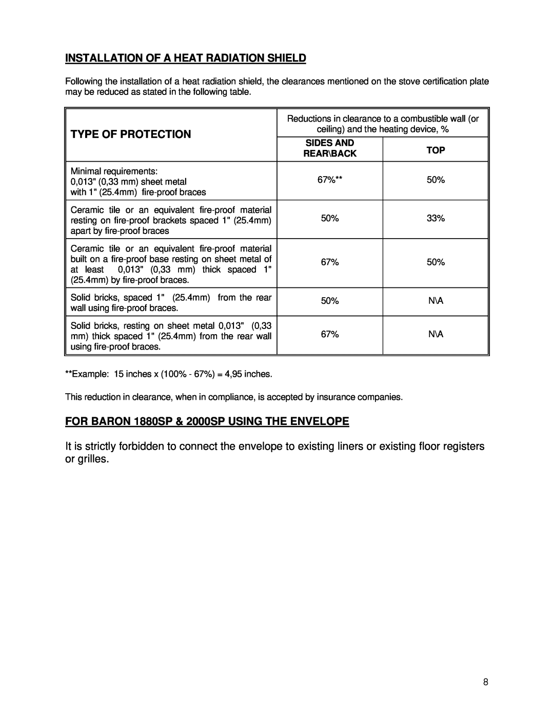
INSTALLATION OF A HEAT RADIATION SHIELD
FOR BARON 1880SP & 2000SP USING THE ENVELOPE
TYPE OF PROTECTION
SIDES AND
STEP BY STEP INSTALLATION OF YOUR CHIMNEY
CHIMNEY
WALL SUPPORT SYSTEM
Chimney
Stove pipe
Page
CEILING SUPPORT SYSTEM
Suitable lengths of stove pipe
Page
COUPLINGS
Page
EXTERIOR AIR INTAKE
AIR CIRCULATION SYSTEM
A Rear Wall Connection
B Floor Connection
BAFFLE BRICK INSTALLATION SAWMAN STOVE ONLY
OPERATING YOUR DROLET WOOD STOVE
FUEL
AVERAGE ENERGY YIELD OF ONE AIR DRIED CORD OF CUT WOOD
High Energy Yield
IGNITION
Before your first fire
HEATING
MAINTENANCE OF THE HEATING SYSTEM
MAINTENANCE OF THE STOVE
PROCEDURES IN CASE OF FIRE
MAINTENANCE OF THE CHIMNEY
IN CASE OF FIRE
CALL IMMEDIATELY THE FIRE DEPARTMENT
FREQUENTLY ASKED QUESTIONS
WHAT DO THE WORDS “DRAFT” AND “NEGATIVE PRESSURE” MEAN?
DRAWING #1
DRAWING #2
DRAWING #3
DRAWING #4
DRAWING #5
CAN I MODIFY MY STOVE TO INSTALL A GLASS DOOR?
WHEN DO IN NEED TO REPLACE THE FIREBRICKS?
LIMITED LIFETIME WARRANTY
WARRANTY APPLICATION
PARTS
LABOUR
Top
Page
Image
Contents