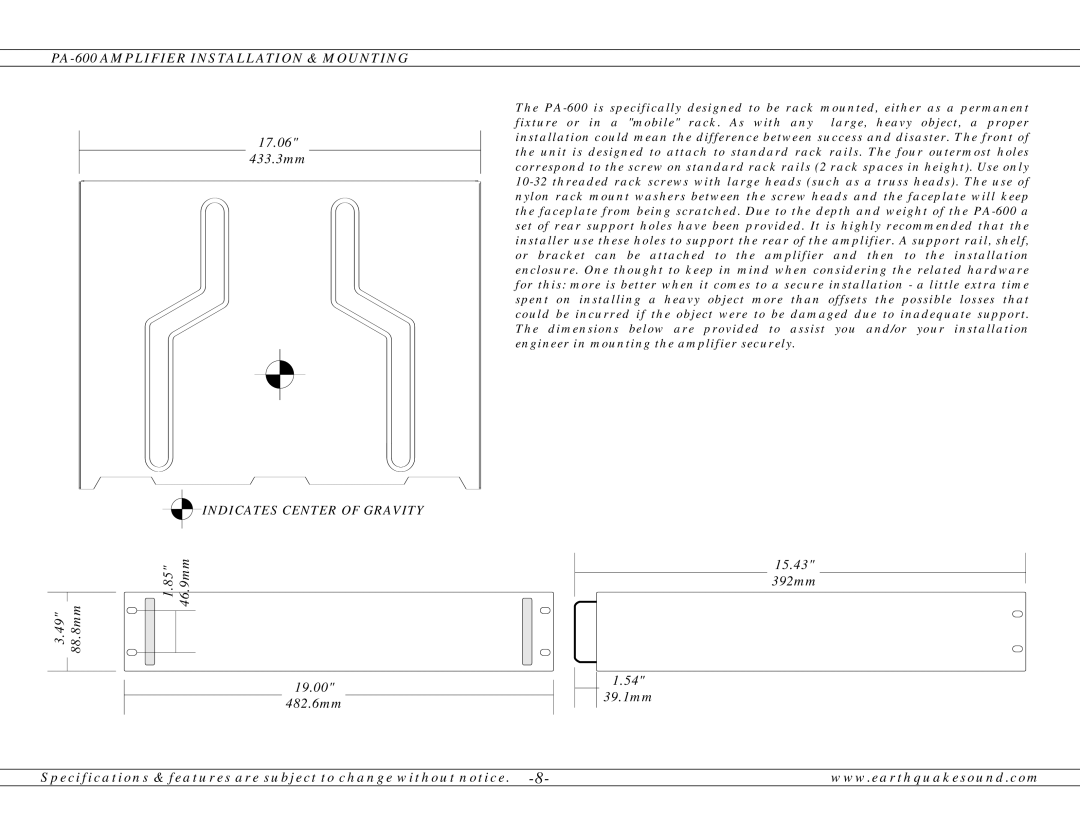
PA-600 specifications
The Earthquake Sound PA-600 is a powerful and versatile amplifier designed for professional audio applications, offering robust performance and a range of features that enhance audio playback. This model is tailored for both live sound environments and permanent installations, making it a preferred choice among sound engineers and venues alike.One of the standout characteristics of the PA-600 is its impressive power output. It delivers a substantial 600 watts of peak power, capable of driving speakers at high volumes without distortion, ensuring that every note is clear and impactful. This makes it an excellent option for powering larger PA systems, where clean and loud sound projection is essential.
The PA-600 features a Class A/B amplifier design that strikes a balance between efficiency and sound quality. This technology ensures that the amplifier runs cool even under heavy loads, providing reliability during extended use. Additionally, the intelligent design reduces signal distortion and maintains audio fidelity, making it suitable for a wide range of musical genres, from rock to classical.
It also comes equipped with various inputs and outputs, including XLR, 1/4-inch TRS, and RCA ports, allowing for seamless integration with different audio sources. The dual-channel configuration enables simultaneous connection of multiple devices, catering to complex audio setups.
Another notable feature is the built-in protection circuitry, which safeguards against overheating, short circuits, and overloads. This ensures the longevity of the amplifier and prevents damage to both the unit and connected speakers. The unit also includes adjustable EQ controls, allowing users to tailor the sound to their specific requirements.
The compact design of the PA-600 makes it easy to transport and install, while its rugged construction ensures durability in demanding environments. With a sleek finish, it also has an aesthetic appeal that blends well with other audio equipment.
Overall, the Earthquake Sound PA-600 amplifies the audio experience, combining power, versatility, and reliability. Its advanced technologies and thoughtful design make it ideal for both amateur and professional use, proving to be a valuable asset in any sound system setup. Whether in a concert hall or a mobile rig, the PA-600 is engineered to deliver outstanding performance and a reliable audio experience.

