Instructional Booklet
Page 4 | Effective: June 2007 |
Instruction Manual for the Eaton
26.Utility - Monitoring and Protection
This feature provides Utility monitoring and protection functions. If the Utility power source fails, then the RTC- 50 will begin the sequence of operations necessary to transfer the load circuit to the Generator power source. All Feature 26 monitoring and protection functions are fail- safe operations.
26D. Go To Generator
This feature provides the capability for an external contact closure to initiate a transfer from Utility to Generator. After the Generator becomes available, TDNE will time out before the transfer to Generator takes place.
26P. All Phase Undervoltage Protection
Dropout: 168 Vac (70% of 240 Vac nominal)
Pickup: 192 Vac (80% of 240 Vac nominal)
SECTION 2:HARDWARE DESCRIPTION
2.1 General
The purpose of this section is to familiarize the reader with the
2.2 LED Indicators
•Utility Available
The green Utility Available LED illuminates if the utility power source meets the criteria to be considered “available”. That is, when it is within its undervoltage range.
•Generator Available
The red Generator Available LED illuminates if the generator power source meets the criteria to be considered “available”. That is, when it is within its undervoltage range.
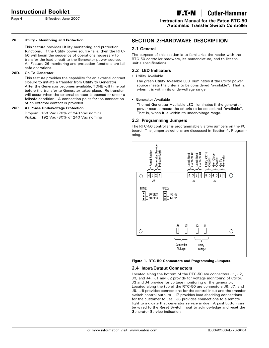
2.3 Programming Jumpers
The
Figure 1. RTC-50 Connectors and Programming Jumpers.
2.4 Input/Output Connectors
Located along the bottom of the
Located along the top of the
For more information visit: www.eaton.com |